RL78/F13, F14 CHAPTER 6 TIMER ARRAY UNIT
R01UH0368EJ0210 Rev.2.10 453
Dec 10, 2015
6.3.7 Timer channel stop register m (TTm)
The TTm register is a trigger register that is used to stop the counting operation of each channel.
When a bit of this register is set to 1, the corresponding bit of timer channel enable status register m (TEm) is cleared to
0. The TTmn, TTHm1, TTHm3 bits are immediately cleared when operation is stopped (TEmn, TTHm1,
TTHm3 = 0), because they are trigger bits.
The TTm register can be set by a 16-bit memory manipulation instruction.
Set the lower 8 bits of the TTm register with a 1-bit or 8-bit memory manipulation instruction with TTmL.
Reset signal generation clears this register to 0000H.
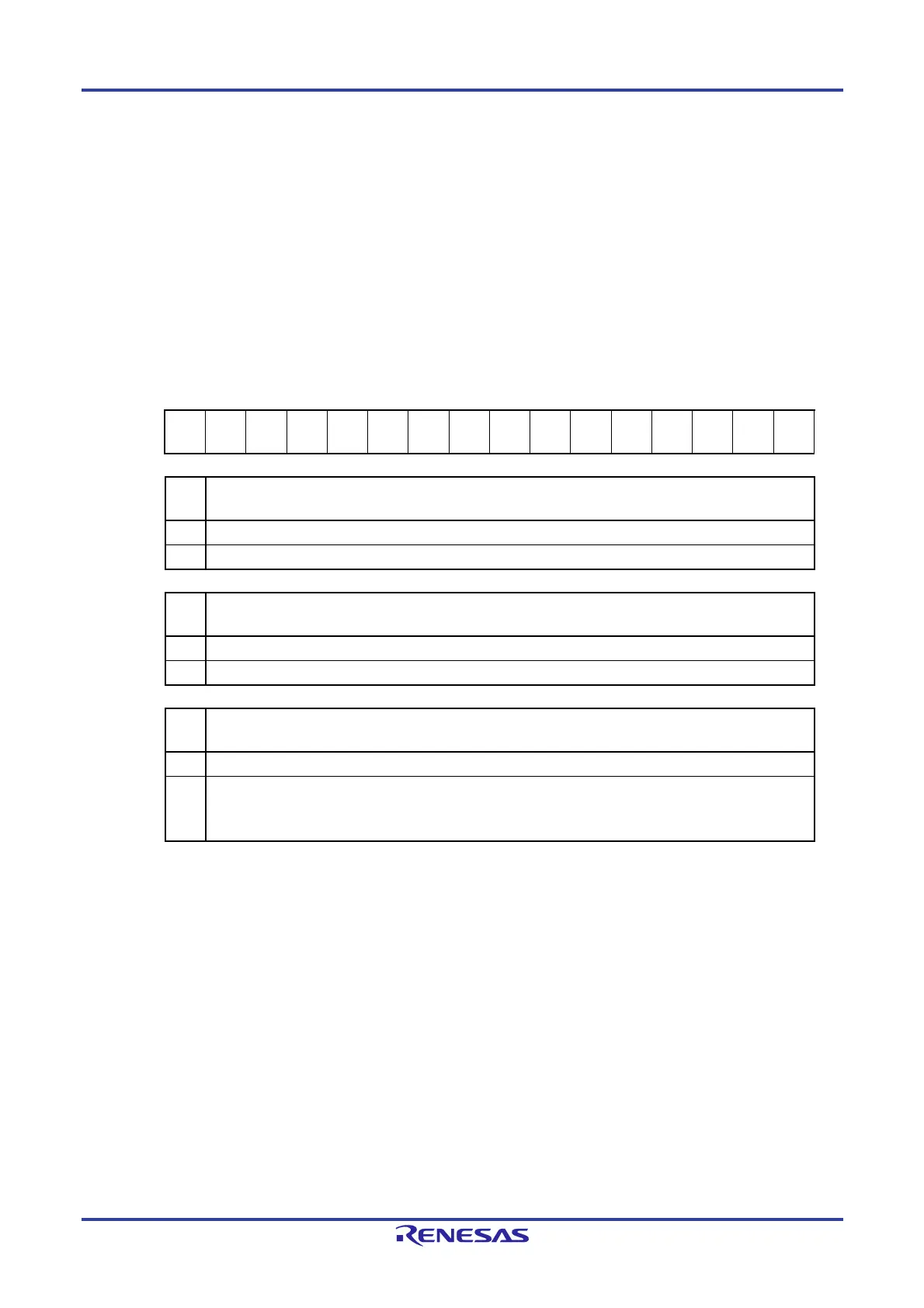
Figure 6-17. Format of Timer Channel Stop Register m (TTm)
Address: F01B4H, F01B5H (TT0), F01F4H, F01F5H (TT1) After reset: 0000H R/W
Symbol 15 14 13 12 11 10 9 8 7 6 5 4 3 2 1 0
TTm 0 0 0 0
TTHm
3
0
TTHm
1
0
TTm
7
TTm
6
TTm
5
TTm
4
TTm
3
TTm
2
TTm
1
TTm
0
TTH
m3
Trigger to stop operation of the higher 8-bit timer when channel 3 is in the 8-bit timer mode
0 No trigger operation
1 Operation is stopped (stop trigger is generated).
TTH
m1
Trigger to stop operation of the higher 8-bit timer when channel 1 is in the 8-bit timer mode
0 No trigger operation
1 Operation is stopped (stop trigger is generated).
TTm
n
Operation stop trigger of channel n
0 No trigger operation
1 Operation is stopped (stop trigger is generated).
This bit is the trigger to stop operation of the lower 8-bit timer for TTm1 and TTm3 when channel 1 or 3 is in
the 8-bit timer mode.
Cautions 1. Be sure to clear bits 15 to 12, 10, and 8 of the TTm register to “0”.
2. Be sure to clear TT1n (n = 7 to 4) to “0” in the Group B, C, and D products.
Remarks 1. When the TTm register is read, 0 is always read.
2. m: Unit number (m = 0, 1),n: Channel number (n = 0 to 7)
3. TT1n is not provided in the Group A products.
TT17 to TT14 are not provided in the Group B, C, and D products.

 Loading...


