RL78/F13, F14 CHAPTER 9 REAL-TIME CLOCK
R01UH0368EJ0210 Rev.2.10 675
Dec 10, 2015
9.3.17 Alarm minute register (ALARMWM)
This register is used to set minutes of alarm.
Set the ALARMWM register by an 8-bit memory manipulation instruction.
Reset signal generation clears this register to 00H.
Caution Set a decimal value of 00 to 59 to this register in BCD code. If a value outside the range is set, the
alarm is not detected.
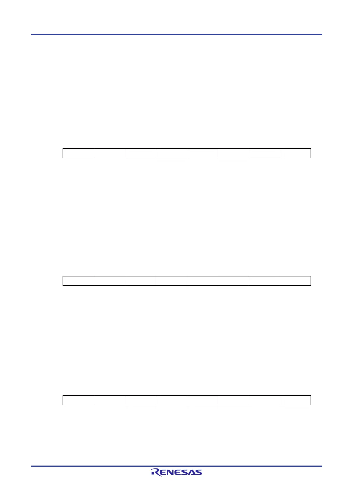
Figure 9-18. Format of Alarm Minute Register (ALARMWM)
Address: FFF9AH After reset: 00H R/W
Symbol 7 6 5 4 3 2 1 0
ALARMWM 0 WM40 WM20 WM10 WM8 WM4 WM2 WM1
9.3.18 Alarm hour register (ALARMWH)
This register is used to set hours of alarm.
Set the ALARMWH register can be set by an 8-bit memory manipulation instruction.
Reset signal generation clears this register to 12H.
However, the value of this register is 00H if the AMPM bit is set to 1 after reset.
Caution Set a decimal value of 00 to 23, 01 to 12, or 21 to 32 to this register in BCD code. If a value outside
the range is set, the alarm is not detected.
Figure 9-19. Format of Alarm Hour Register (ALARMWH)
Address: FFF9BH After reset: 12H R/W
Symbol 7 6 5 4 3 2 1 0
ALARMWH 0 0 WH20 WH10 WH8 WH4 WH2 WH1
Caution Bit 5 (WH20) of the ALARMWH register indicates AM(0)/PM(1) if AMPM = 0 (if the 12-hour system
is selected).
9.3.19 Alarm week register (ALARMWW)
This register is used to set date of alarm.
Set the ALARMWW register by an 8-bit memory manipulation instruction.
Reset signal generation clears this register to 00H.
Figure 9-20. Format of Alarm Week Register (ALARMWW)
Address: FFF9CH After reset: 00H R/W
Symbol 7 6 5 4 3 2 1 0
ALARMWW 0 WW6 WW5 WW4 WW3 WW2 WW1 WW0

 Loading...


