RL78/F13, F14 CHAPTER 9 REAL-TIME CLOCK
R01UH0368EJ0210 Rev.2.10 662
Dec 10, 2015
9.3.4 Timer input select register 2 (TIS2)
The TIS2 register selects an input source of the timer array unit 1.
The TIS23 and TIS22 bits in the TIS2 register are used in conjunction with the real time clock to implement the watch
error correction in channels 7 and 6. When the TIS23 bit is set to 1, the RTC1HZ output signal is selected for the timer input
of channel 7. When the TIS22 bit is set to 1, the RTC1HZ output signal is selected for the timer input of channel 6.
Set the TIS2 register by an 8-bit memory manipulation instruction.
Reset signal generation clears this register to 00H.
This function is valid only for the Group E products.
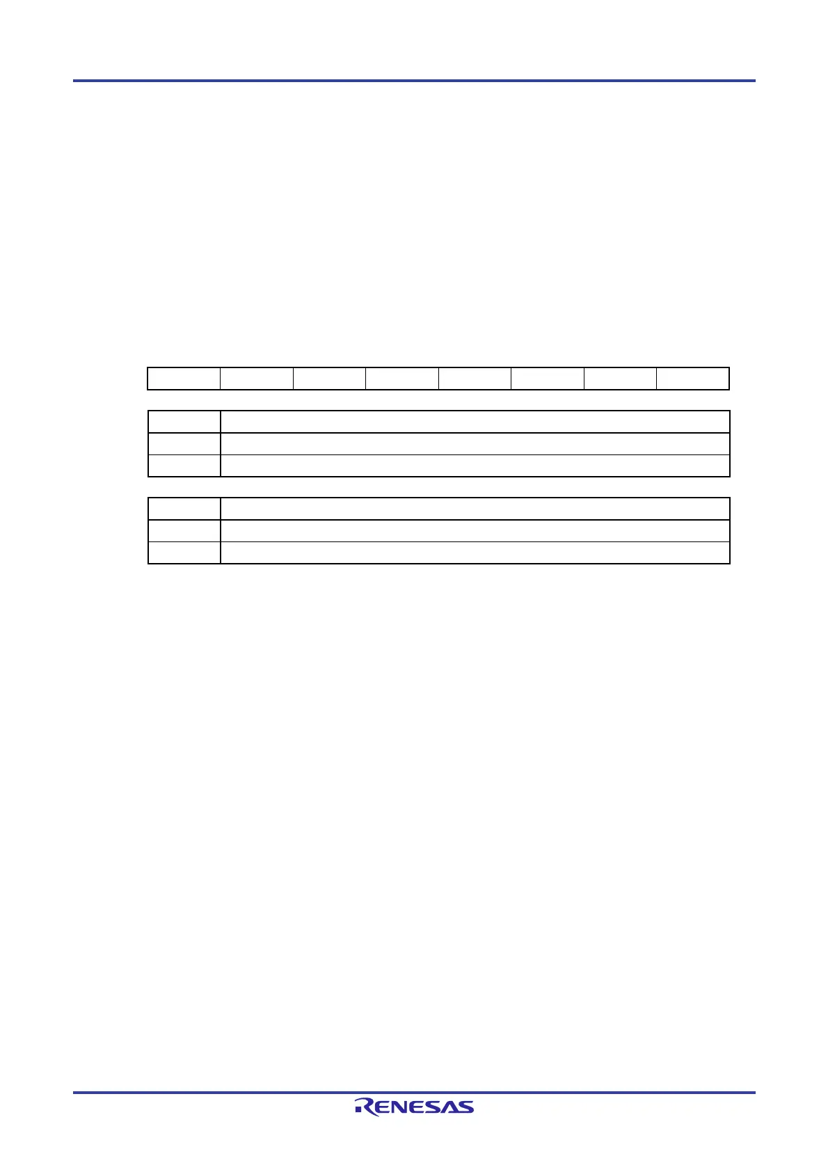
Figure 9-5. Format of Timer Input Select Register 2 (TIS2)
Address: F007AH After reset: 00H R/W
Symbol 7 6 5 4 3 2 1 0
TIS2 0 0 0 0 TIS23 TIS22 0 0
TIS22 Selection of timer input used with channel 6 of timer array unit 1
0 Input signal of timer input pin (TI16)
1 RTC1HZ output signal
TIS23 Selection of timer input used with channel 7 of timer array unit 1
0 Input signal of timer input pin (TI17)
1 RTC1HZ output signal
Cautions 1. Do not change the select bit of the timer input while inputting data to the TImn pin (m = 0,
1; n = 0 to 7).
2. When selecting the RTC1HZ output signal for the clock source of the timer input used in
channels 7 and 6 in the TAU, set the TIS23 and TIS22 bits to 1 and select the RTC1HZ
output signal for the timer input of channels 7 and 6.

 Loading...


