RL78/F13, F14 CHAPTER 7 TIMER RJ
R01UH0368EJ0210 Rev.2.10 549
Dec 10, 2015
7.3.5 Timer RJ Control Register 0 (TRJCR0)
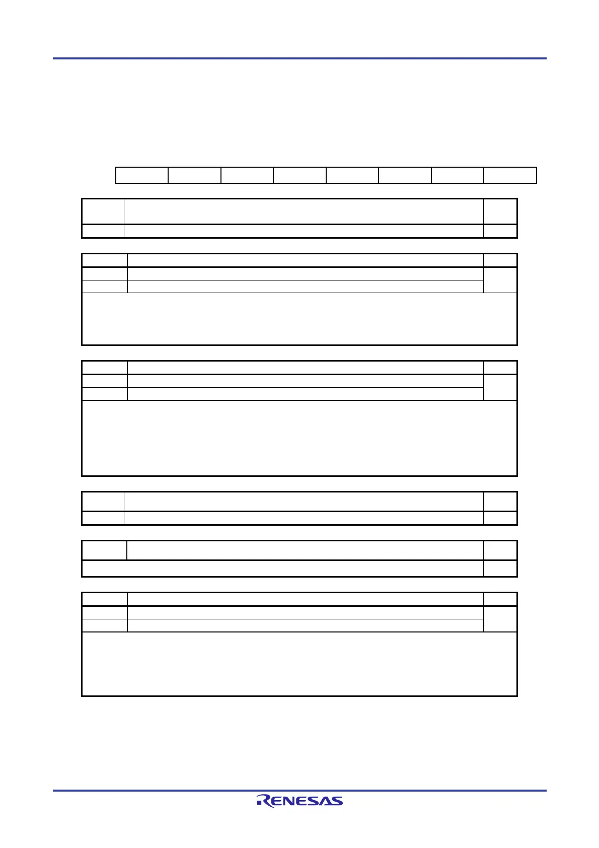
Figure 7-6. Format of Timer RJ Control Register 0 (TRJCR0)
Address : F0240H After Reset: 00H
Symbol 7 6 5 4 3 2 1 0
TRJCR0 — — TUNDF TEDGF — TSTOP TCSTF TSTART
Bits
7 to 6
Nothing is assigned R/W
— The write value must be 0. The read value is 0. R
TUNDF
Timer RJ underflow flag
Note 1
R/W
0 No underflow R/W
1 Underflow
[Condition for setting to 0]
• When 0 is written to this bit by a program.
[Condition for setting to 1]
• When the counter underflows.
TEDGF
Active edge judgement flag
Notes 1, 2
R/W
0 No active edge received R/W
1 Active edge received
[Condition for setting to 0]
• When 0 is written to this bit by a program.
[Conditions for setting to 1]
• When the measurement of the active width of the external input (TRJIO0) is completed in pulse
width measurement mode.
• The set edge of the external input (TRJIO0) is input in pulse period measurement mode.
Bit 3 Nothing is assigned R/W
— The write value must be 0. The read value is 0. R
TSTOP
Timer RJ count forced stop
Note 3
R/W
When 1 is written to this bit, the count is forcibly stopped. The read value is 0.
W
TCSTF
Timer RJ count status flag
Note 4
R/W
0 Count stops R
1 Count in progress
[Conditions for setting to 0]
• When 0 is written to the TSTART bit (the TCSTF bit is set to 0 in synchronization with the count source).
• When 1 is written to the TSTOP bit.
[Condition for setting to 1]
• When 1 is written to the TSTART bit (the TCSTF bit is set to 1 in synchronization with the count source).
(Notes are listed on the next page.)

 Loading...


