RL78/F13, F14 CHAPTER 6 TIMER ARRAY UNIT
R01UH0368EJ0210 Rev.2.10 427
Dec 10, 2015
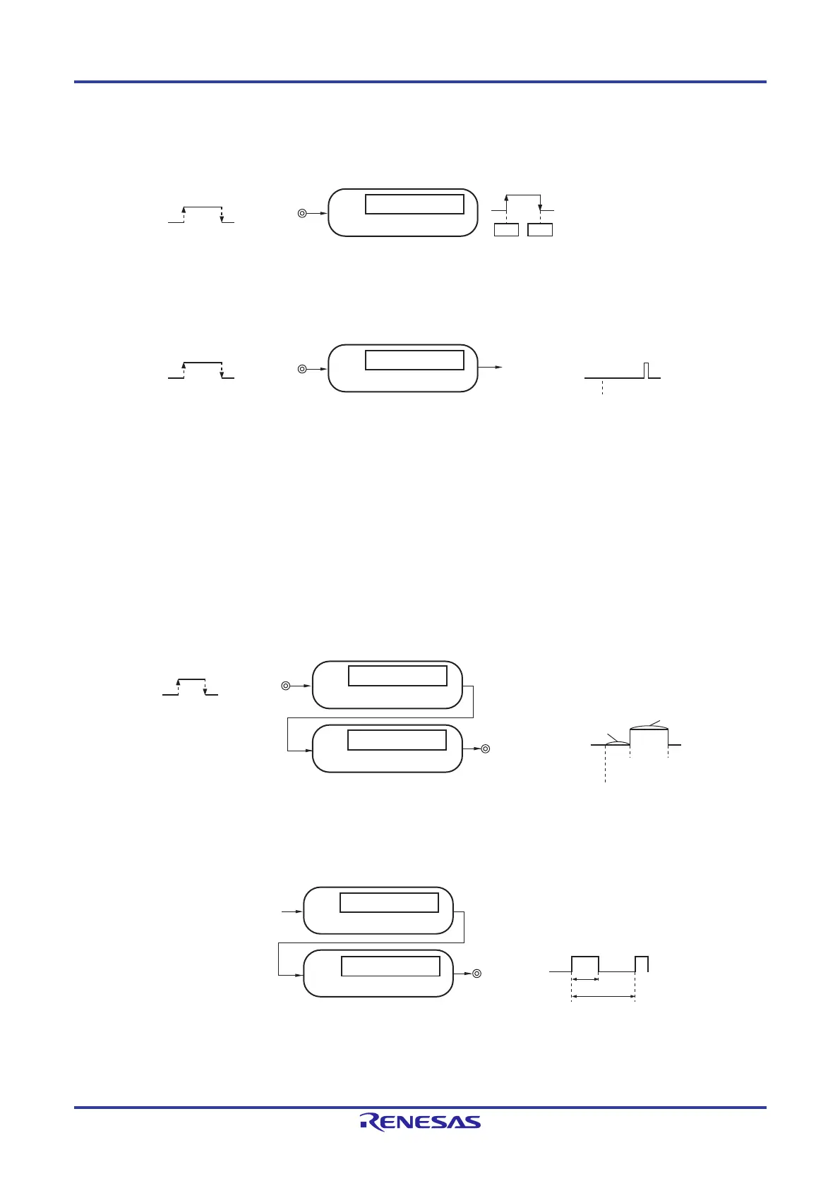
(6) Measurement of high-/low-level width of input signal
Counting is started by a single edge of the signal input to the timer input pin (TImn), and the count value is captured
at the other edge. In this way, the high-level or low-level width of the input signal can be measured.
(7) Delay counter
Counting is started at the valid edge of the signal input to the timer input pin (TImn), and an interrupt is generated
after any delay period.
Remarks 1 m: Unit number (m = 0, 1), n: Channel number (n = 0 to 7)
2. The presence or absence of timer I/O pins of channels 0 to 7 depends on the product. See Table 6-2 Timer
I/O Pins provided in Each Product for details.
6.1.2 Simultaneous channel operation function
By using the combination of a master channel (a reference timer mainly controlling the cycle) and slave channels (timers
operating according to the master channel), channels can be used for the following purposes.
(1) One-shot pulse output
Two channels are used as a set to generate a one-shot pulse with a specified output timing and a specified pulse
width.
(2) PWM (Pulse Width Modulation) output
Two channels are used as a set to generate a pulse with a specified period and a specified duty factor.
(Caution and Remark are is listed on the next page.)
Edge detection
Timer input
(TImn)
Capture
xxH
00H
Start
Channel n
Capture operation
Edge detection
Timer input
(TImn)
Channel n
Compare operation
Interrupt signal
(INTTMmn)
Start
Timer output
(TOmp)
Interrupt signal (INTTMmn)
Edge detection
Timer input
(TImn)
Toggle
(Master)
Output
timing
Pulse width
Start
(Master)
Toggle
(Slave)
Channel n (master)
Channel p (slave)
Compare operation
Compare operation
Operation clock
Duty
Period
Compare operation
Compare operation
Channel n (master)
Channel p (slave)
Timer output
(TOmp)
Interrupt signal (INTTMmn)
 Loading...


