RL78/F13, F14 CHAPTER 17 LIN/UART MODULE (RLIN3)
R01UH0368EJ0210 Rev.2.10 1256
Dec 10, 2015
17.8 Noise Filter
The LIN/UART module has a noise filter for reducing erroneous receiving of data due to noise. By setting the LRDNFS bit
in the LMDn register to 0 (to use the noise filter), the noise filter is activated. The noise filter samples the level of the
synchronized LRXDn (n = 0, 1) based on the prescaler clock, and outputs the majority among three sampled levels. The
value of each bit in the received data is determined by the noise filter output.
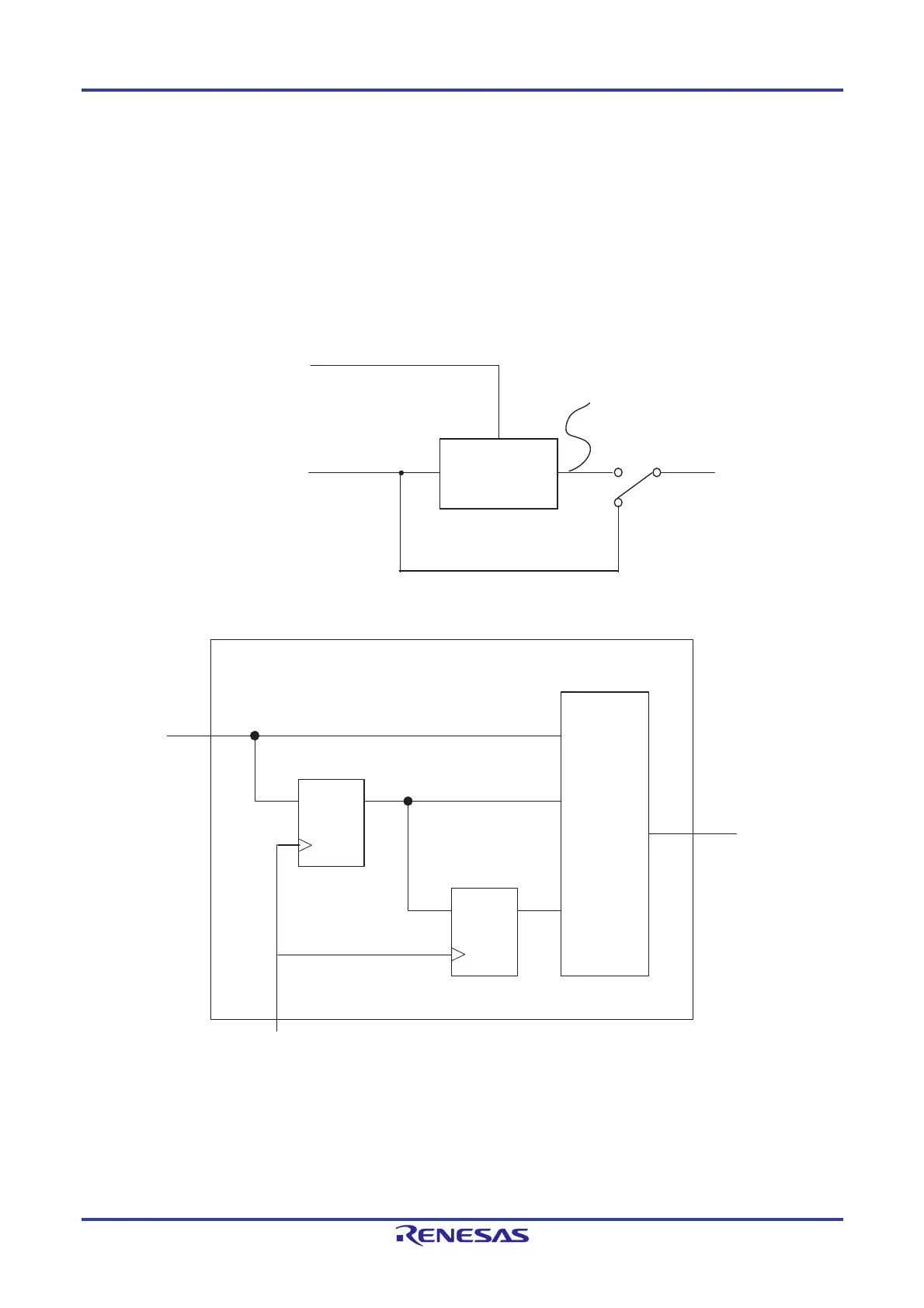
Figure 17-44 shows the configuration of the noise filter, figure 17-45 an example of a noise filter circuit, and figure 17-46 the
determination of the received data when the noise filter is used.
Figure 17-44. Configuration of Noise Filter
Figure 17-45. Example of Noise Filter Circuit
Noise filter
(decision by
majority of
3 sampling)
Prescaler clock
Synchronized
LRXDn (n = 0, 1)
LRDNFS bit in
LMDn register
0
1
Noise filter output
Majority
circuit
Synchronized
LRXDn (n = 0, 1)
Noise filter output
Prescaler clock
FF1
FF2
Noise filter

 Loading...


