EasyManuals Logo

Renesas RL78 Series User Manual

Renesas RL78 Series
1879 pages
To Next Page IconTo Next Page
To Previous Page IconTo Previous Page
Page #723 background imageLoading...
Page #723 background image
RL78/F13, F14 CHAPTER 10 CLOCK OUTPUT/BUZZER OUTPUT CONTROLLER
R01UH0368EJ0210 Rev.2.10 691
Dec 10, 2015
10.3.3 Port mode register 14 (PM14)
These registers set input/output of port in 1-bit units.
When using the P140/PCLBUZ0 pins for clock output and buzzer output, clear PM140 bit and the output latch of
P140 to 0.
The PM14 register can be set by a 1-bit or 8-bit memory manipulation instruction.
Reset signal generation sets these registers to FFH.
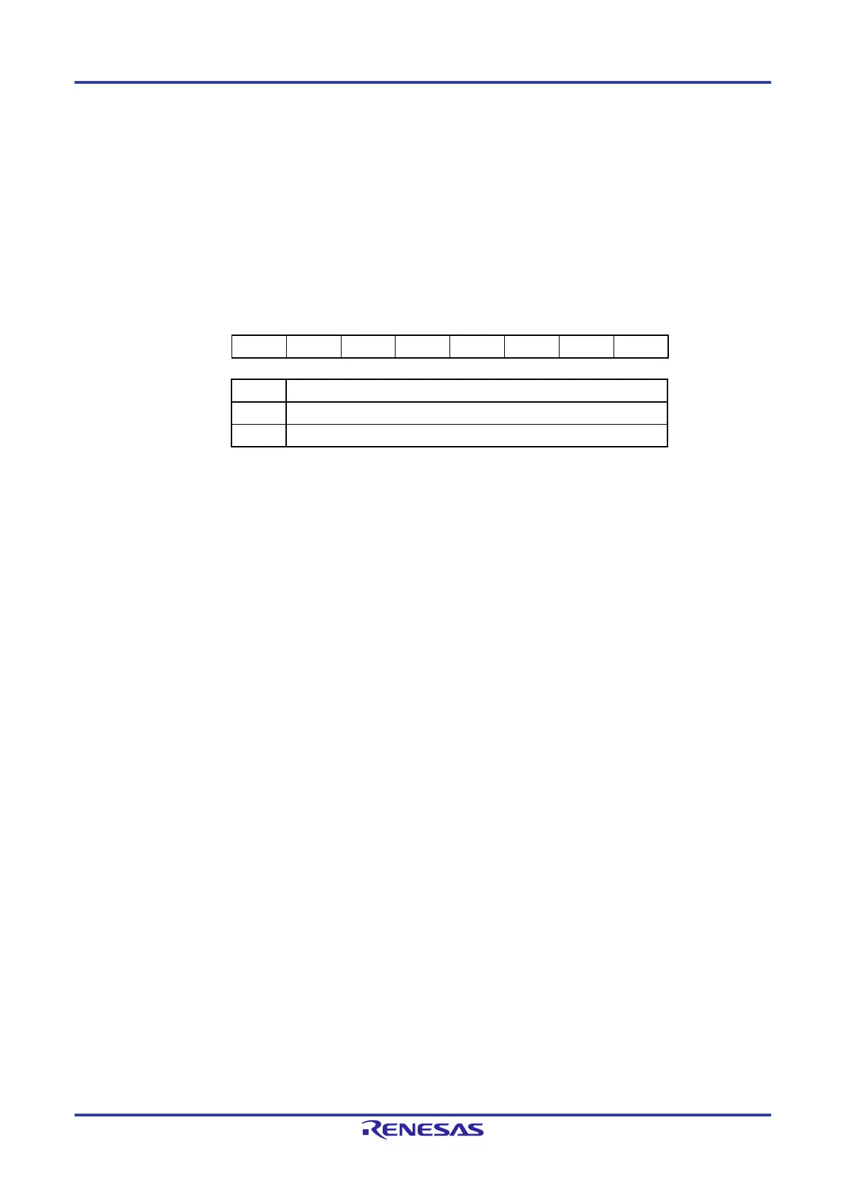
Figure 10-4. Format of Port Mode Register 14 (PM14)
Address: FFF2EH After reset: FFH R/W
Symbol 7 6 5 4 3 2 1 0
PM14 1 1 1 1 1 1 1 PM140
PMmn Pmn pin I/O mode selection (mn = 140)
0 Output mode (output buffer on)
1 Input mode (output buffer off)

Table of Contents

Other manuals for Renesas RL78 Series

Questions and Answers:

Question and Answer IconNeed help?

Do you have a question about the Renesas RL78 Series and is the answer not in the manual?

Renesas RL78 Series Specifications

General IconGeneral
CoreRL78
CPU Clock SpeedUp to 32 MHz
Flash MemoryUp to 512 KB
RAMUp to 32 KB
Operating Voltage1.6 V to 5.5 V
Low Power ModesHALT, STOP, SNOOZE
CPU Architecture16-bit
Temperature Range-40°C to +85°C
PackageLQFP
Timers16-bit timers
Communication InterfacesUART, I2C, LIN
A/D Converter12-bit

Related product manuals