RL78/F13, F14 CHAPTER 9 REAL-TIME CLOCK
R01UH0368EJ0210 Rev.2.10 664
Dec 10, 2015
9.3.6 Real-time clock control register 0 (RTCC0)
The RTCC0 register is an 8-bit register that is used to start or stop the real-time clock operation, control the RTC1HZ pin,
and set a 12- or 24-hour system and the constant-period interrupt function.
Set the RTCC0 register by a 1-bit or 8-bit memory manipulation instruction.
Reset signal generation clears this register to 00H.
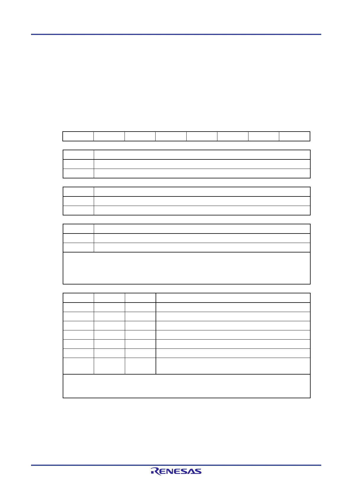
Figure 9-7. Format of Real-time Clock Control Register 0 (RTCC0)
Address: FFF9DH After reset: 00H R/W
Symbol <7> 6 <5> 4 3 2 1 0
RTCC0 RTCE 0 RCLOE1 0 AMPM CT2 CT1 CT0
RTCE Real-time clock operation control
0 Stops counter operation.
1 Starts counter operation.
RCLOE1 RTC1HZ pin output control
0 Disables output of the RTC1HZ pin (1 Hz).
1 Enables output of the RTC1HZ pin (1 Hz).
AMPM Selection of 12-/24-hour system
0 12-hour system (a.m. and p.m. are displayed.)
1 24-hour system
Rewrite the AMPM bit value after setting the RWAIT bit (bit 0 of real-time clock control register 1 (RTCC1)) to 1. If
the AMPM bit value is changed, the values of the hour count register (HOUR) change according to the specified
time system.
Table 9-2 shows the displayed time digits that are displayed.
CT2 CT1 CT0 Constant-period interrupt (INTRTC) selection
0 0 0 Does not use fixed-cycle interrupt function.
0 0 1 Once per 0.5 s (synchronized with second count up)
0 1 0 Once per 1 s (same time as second count up)
0 1 1 Once per 1 m (second 00 of every minute)
1 0 0 Once per 1 hour (minute 00 and second 00 of every hour)
1 0 1 Once per 1 day (hour 00, minute 00, and second 00 of every day)
1 1
Once per 1 month (Day 1, hour 00 a.m., minute 00, and second 00 of
every month)
When changing the values of the CT2 to CT0 bits while the counter operates (RTCE = 1), rewrite the values of the
CT2 to CT0 bits after disabling interrupt servicing INTRTC by using the interrupt mask flag register. Furthermore,
after rewriting the values of the CT2 to CT0 bits, enable interrupt servicing after clearing the RIFG and RTCIF flags.
Caution Do not change the value of the RTCLOE1 bit when RTCE = 1.
Remark : don’t care

 Loading...


