RL78/F13, F14 CHAPTER 17 LIN/UART MODULE (RLIN3)
R01UH0368EJ0210 Rev.2.10 1102
Dec 10, 2015
CHAPTER 17 LIN/UART MODULE (RLIN3)
17.1 Overview
The LIN/UART module is a hardware LIN communication controller that supports LIN Specification Package Revision 1.3,
2.0, 2.1, 2.2 and SAE J2602, and automatically performs frame communication and error determination.
The LIN/UART module is provided with UART mode and can also be used as a UART.
Table 17-1 gives the LIN/UART module specifications and Figures 17-1 and 17-2 show block diagrams of the LIN/UART
module.
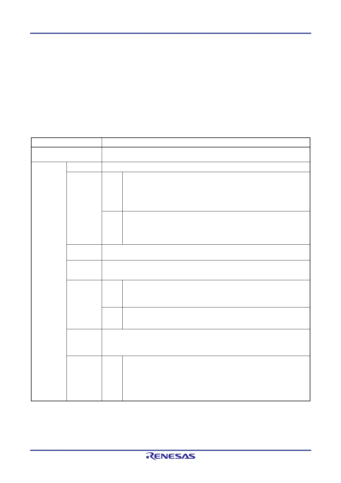
Table 17-1. LIN/UART Module Specifications
Item Specifications
Channel count RL78/F13: 1 channel
RL78/F14: 1 to 2 channels
LIN
communication
function
Protocol
LIN Specification Package Revision 1.3, 2.0, 2.1, 2.2 and SAE J2602
Variable frame
structure
Master
Break (low) transmission width: 13 to 28 Tbits
Break delimiter transmission width: 1 to 4 Tbits
Inter-byte space (header): 0 to 7 Tbits (space between Sync field and ID field)
Note 1
Response space: 0 to 7 Tbits
Note 1
Inter-byte space: 0 to 3 Tbits (space between data bytes in response area)
Wake-up: 1 to 16 Tbits
Slave
Break reception width: 9.5 or 10.5 Tbits [for fixed baud rate]
: 10 or 11 Tbits [for auto baud rate]
Response space: 0 to 7 Tbits
Inter-byte space: 0 to 3 Tbits (space between data bytes in response area)
Wake-up: 1 to 16 Tbits
Checksum
Automatic operation for both transmission and reception
Classic or enhanced selectable (for each frame)
Response field
data byte
count
Variable from 0 to 8 bytes
Multi-byte (9 or more bytes) response transmission and reception also possible
Frame
communication
modes
Master
Mode in which header transmission and response transmission/reception is started
with a single transmission start request
Mode in which header transmission and response transmission are started with
separate transmission start requests (frame separate mode)
Slave
Mode in which header is automatically received with fixed baud rate
Mode in which header is automatically received with the baud rate set according to the
sync field measurement result of the sync field and break field detected
Wake-up
transmission
and reception
LIN wake-up mode provided
Wake-up transmission (1 to 16 Tbits)
Wake-up reception
Low width of input signals measured
Status
Master
Successful frame/wake-up transmission
Successful header transmission
Successful frame/wake-up reception
Note 2
Successful data 1 reception
Error detection
Operation mode
(LIN reset mode, LIN wake-up mode, LIN operation mode, LIN self-test mode)

 Loading...


