RL78/F13, F14 CHAPTER 16 SERIAL INTERFACE IICA
R01UH0368EJ0210 Rev.2.10 1030
Dec 10, 2015
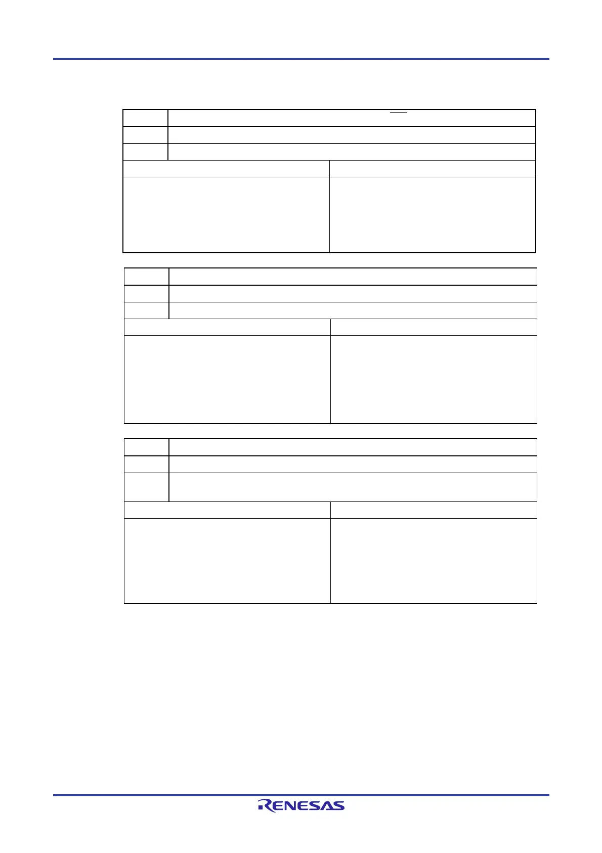
Figure 16-7. Format of IICA Status Register 0 (IICS0) (3/3)
ACKD0 Detection of acknowledge (ACK)
0 Acknowledge was not detected.
1 Acknowledge was detected.
Condition for clearing (ACKD0 = 0) Condition for setting (ACKD0 = 1)
When a stop condition is detected
At the rising edge of the next byte’s first clock
Cleared by LREL0 = 1 (exit from communications)
When the IICE0 bit changes from 1 to 0 (operation
stop)
Reset
After the SDAA0 line is set to low level at the rising
edge of SCLA0 line’s ninth clock
STD0 Detection of start condition
0 Start condition was not detected.
1 Start condition was detected. This indicates that the address transfer period is in effect.
Condition for clearing (STD0 = 0) Condition for setting (STD0 = 1)
When a stop condition is detected
At the rising edge of the next byte’s first clock
following address transfer
Cleared by LREL0 = 1 (exit from communications)
When the IICE0 bit changes from 1 to 0 (operation
stop)
Reset
When a start condition is detected
SPD0 Detection of stop condition
0 Stop condition was not detected.
1 Stop condition was detected. The master device’s communication is terminated and the bus is
released.
Condition for clearing (SPD0 = 0) Condition for setting (SPD0 = 1)
At the rising edge of the address transfer byte’s first
clock following setting of this bit and detection of a
start condition
When the WUP0 bit changes from 1 to 0
When the IICE0 bit changes from 1 to 0 (operation
stop)
Reset
When a stop condition is detected
Remark LREL0: Bit 6 of IICA control register 00 (IICCTL00)
IICE0: Bit 7 of IICA control register 00 (IICCTL00)
16.3.4 IICA flag register 0 (IICF0)
This register sets the operation mode of I
2
C and indicates the status of the I
2
C bus.
The IICF0 register can be set by a 1-bit or 8-bit memory manipulation instruction. However, the STT0 clear flag (STCF0)
and I
2
C bus status flag (IICBSY0) bits are read-only.
The IICRSV0 bit can be used to enable/disable the communication reservation function.
The STCEN0 bit can be used to set the initial value of the IICBSY bit.
The IICRSV0 and STCEN0 bits can be written only when the operation of I
2
C is disabled (bit 7 (IICE0) of IICA control
register 00 (IICCTL00) = 0). When operation is enabled, the IICF0 register can be read.
Reset signal generation clears this register to 00H.

 Loading...


