RL78/F13, F14 CHAPTER 9 REAL-TIME CLOCK
R01UH0368EJ0210 Rev.2.10 682
Dec 10, 2015
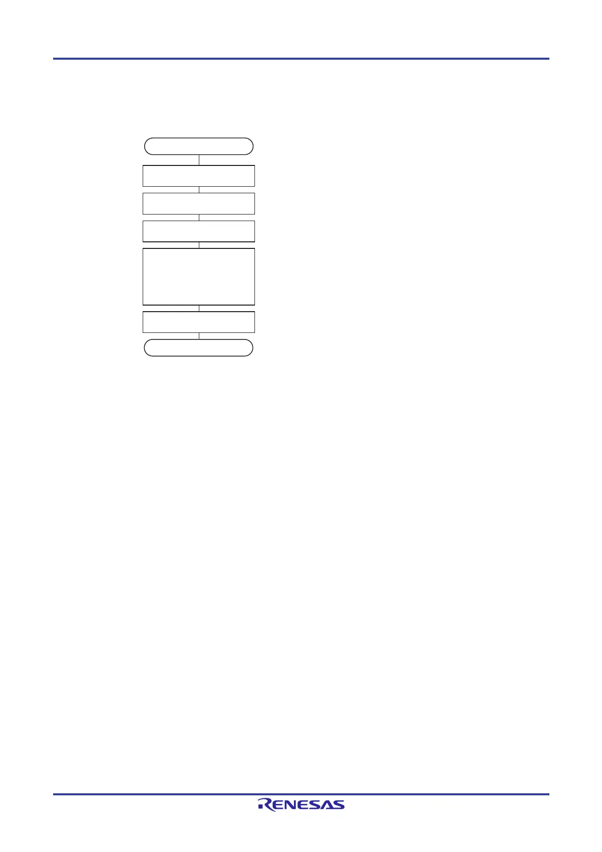
9.4.5 1 Hz output of real-time clock
Figure 9-26. 1 Hz Output Setting Procedure
Note The timer input select register 2 (TIS2) is only available in the RL78/F14 products with 48, 64, or 80 pins and 128
Kbytes to 256 Kbytes of code flash memory or with 100 pins and 64 Kbytes to 256 Kbytes of code flash memory.
Caution First set the RTCEN bit to 1 while oscillation of the input clock (f
RTC) is stable.
Start
PMxx = 0 Sets the port mode register so that the pin is an output.
Pxx = 0 Sets the port register for the output of 0.
TIS14 = 0
TIS17, TIS16 = 0, 0 or 1, 0
TIS22 = 0
Note
TIS23 = 0
Note
RCLOE1 = 1
Enables output of the RTC1HZ pin (1 Hz).
RTCE = 1 Starts counter operation.
Output start from RTC1HZ pin
RTCE = 0
Stops counter operation.

 Loading...


