RL78/F13, F14 CHAPTER 24 RESET FUNCTION
R01UH0368EJ0210 Rev.2.10 1552
Dec 10, 2015
24.1 Register for Confirming Reset Source
24.1.1 Reset control flag register (RESF)
Many internal reset generation sources exist in the RL78/F13 and RL78/F14. The reset control flag register (RESF) is
used to store which source has generated the reset request.
The RESF register can be read by an 8-bit memory manipulation instruction.
RESET input, reset by power-on-reset (POR) circuit, and reading the RESF register clear TRAP, WDCLRF, IAWRF, and
LVIRF flags.
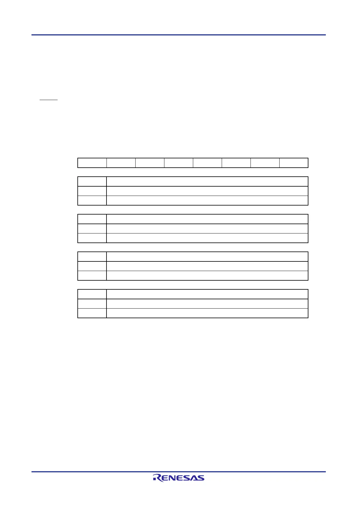
Figure 24-5. Format of Reset Control Flag Register (RESF)
ddress: FFFA8H After reset: 00H
Note 1
R
Symbol 7 6 5 4 3 2 1 0
RESF TRAP 0 0 WDCLRF 0 0 IAWRF LVIRF
TRAP Internal reset request by execution of illegal instruction
Note 2
0 Internal reset request is not generated, or the RESF register is cleared.
1 Internal reset request is generated.
WDCLRF Internal reset request by watchdog timer (WDT) or clock monitor
0 Internal reset request is not generated, or the RESF register is cleared.
1 Internal reset request by the watchdog timer or the clock monitor is generated.
IAWRF Internal reset request by illegal-memory access
0 Internal reset request is not generated, or the RESF register is cleared.
1 Internal reset request is generated.
LVIRF Internal reset request by voltage detector (LVD)
0 Internal reset request is not generated, or the RESF register is cleared.
1 Internal reset request is generated.
Notes 1. The value after reset varies depending on the reset source.
2. The illegal instruction is generated when instruction code FFH is executed.
Reset by the illegal instruction execution not issued by emulation with the in-circuit emulator
or on-chip debug emulator.
Caution Do not read data by a 1-bit memory manipulation instruction.

 Loading...


