RL78/F13, F14 CHAPTER 6 TIMER ARRAY UNIT
R01UH0368EJ0210 Rev.2.10 460
Dec 10, 2015
6.3.14 Timer output mode register m (TOMm)
The TOMm register is used to control the timer output mode of each channel.
When a channel is used for the independent channel operation function, set the corresponding bit of the channel to be
used to 0.
When a channel is used for the simultaneous channel operation function (PWM output, one-shot pulse output, or multiple
PWM output), set the corresponding bit of the master channel to 0 and the corresponding bit of the slave channel to 1.
The setting of each channel n by this register is reflected at the timing when the timer output signal is set or reset while
the timer output is enabled (TOEmn = 1).
The TOMm register can be set by a 16-bit memory manipulation instruction.
Set the lower 8 bits of the TOMm register with an 8-bit memory manipulation instruction with TOMmL.
Reset signal generation clears this register to 0000H.
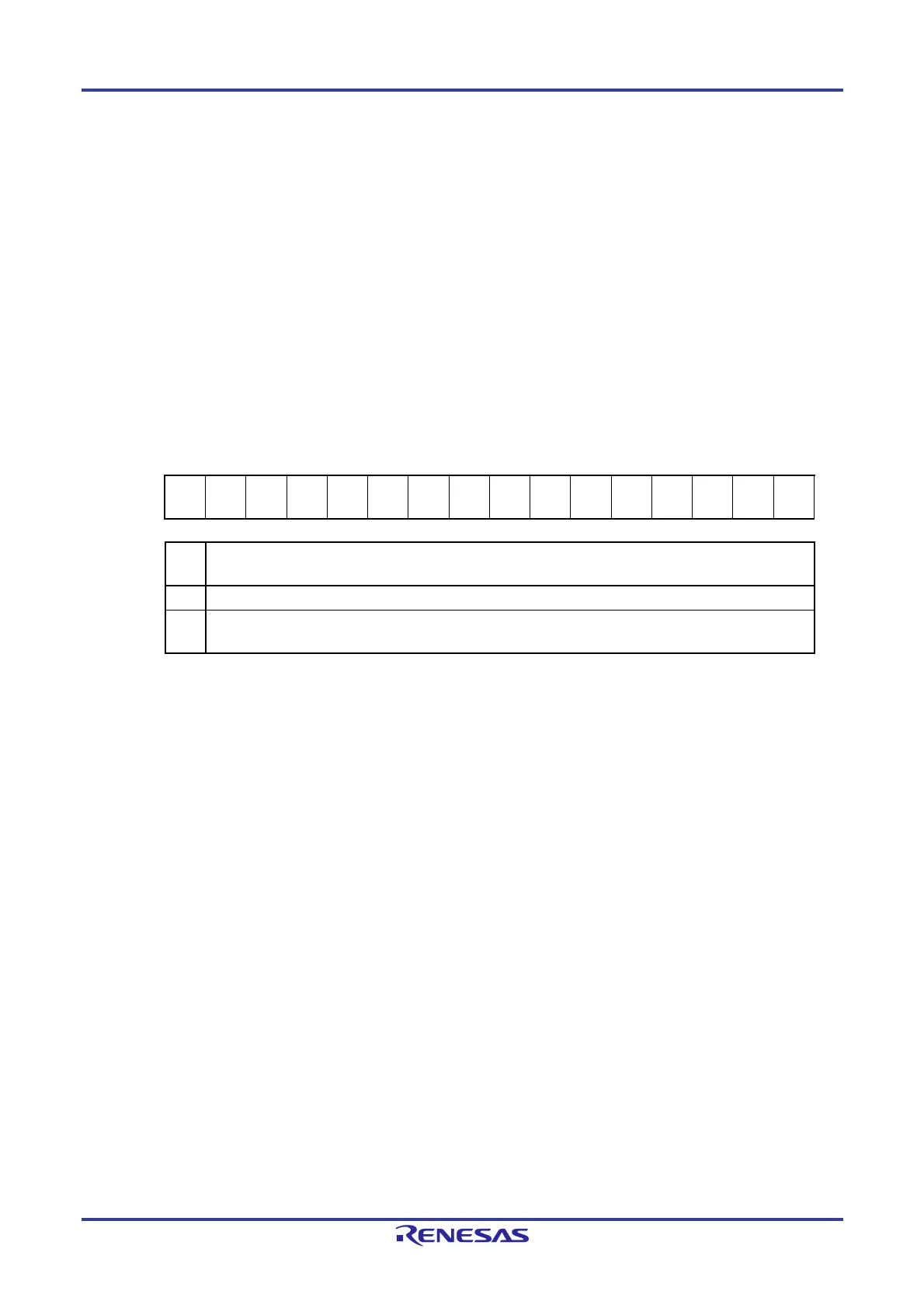
Figure 6-24. Format of Timer Output Mode Register m (TOMm)
Address: F01BEH, F01BFH (TOM0), F01FEH, F01FFH (TOM1) After reset: 0000H R/W
Symbol 15 14 13 12 11 10 9 8 7 6 5 4 3 2 1 0
TOMm 0 0 0 0 0 0 0 0
TOM
m7
TOM
m6
TOM
m5
TOM
m4
TOM
m3
TOM
m2
TOM
m1
0
TOM
mn
Control of timer output mode of channel n
0 Master channel output mode (to produce toggle output by timer interrupt request signal (INTTMmn))
1
Slave channel output mode (output is set by the timer interrupt request signal (INTTMmn) of the master
channel, and reset by the timer interrupt request signal (INTTM0p) of the slave channel)
Caution Be sure to clear bits 15 to 8 and 0 to “0”. (unit 1, 0: Group E products, unit 0: Group A products)
Be sure to clear bits 15 to 8 and 0 of unit 0 and bits 15 to 4 and 0 of unit 1 to "0". (Group B, C, and D
products)
Remarks 1. m: Unit number (m = 0, 1)
n: Channel number
n = 0 to 7 (n = 0, 2, 4, 6 for master channel)
p: Slave channel number
n < p ≤ 7 (For details of the relation between the master channel and slave channel, refer to 6.4.1 Basic
rules of simultaneous channel operation function.)
2. TOM1n is not provided in the Group A products.
TOM17 to TOM14 are not provided in the Group B, C, and D products.

 Loading...


