RL78/F13, F14 CHAPTER 8 TIMER RD
R01UH0368EJ0210 Rev.2.10 637
Dec 10, 2015
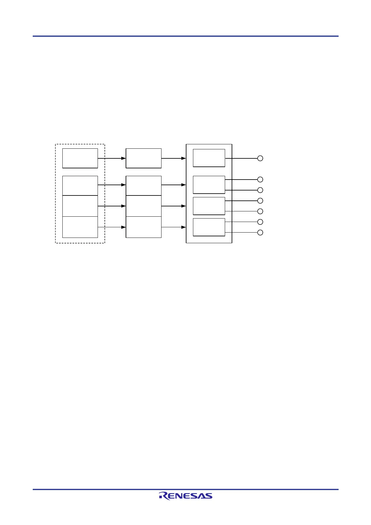
8.3.5 Reset Synchronous PWM Mode
In this mode, three normal-phases and three counter-phases of the PWM waveform are output with the same period
(three-phase, sawtooth wave modulation, and no dead time).
Figure 8-55 shows the Block Diagram of Reset Synchronous PWM Mode, Table 8-17 lists the Reset Synchronous PWM
Mode Specifications, Figure 8-56 shows an Operation Example in Reset Synchronous PWM Mode.
See Figure 8-54 Operation Example in PWM Function (Duty Cycle 0%, Duty Cycle 100%) for an operation example
in PWM Mode with duty cycle 0% and duty cycle 100%.
Figure 8-55. Block Diagram of Reset Synchronous PWM Mode
TRDIOC0
TRDIOB0
TRDIOD0
TRDIOA1
TRDIOC1
TRDIOB1
TRDIOD1
Buffer
(1)
Note:
1. When bits TRDBFC0, TRDBFD0, TRDBFC1, and TRDBFD1 in the TRDMR register are set to 1 (buffer register).
TRDGRC0
register
TRDGRA0
register
Period
Waveform control
PWM1
PWM2
PWM3
Normal-phase
Counter-phase
Normal-phase
Counter-phase
Normal-phase
Counter-phase
TRDGRB0
register
TRDGRA1
register
TRDGRB1
register
TRDGRD0
register
TRDGRC1
register
TRDGRD1
register

 Loading...


