RL78/F13, F14 CHAPTER 6 TIMER ARRAY UNIT
R01UH0368EJ0210 Rev.2.10 503
Dec 10, 2015
6.7.4 Operation as input pulse interval measurement
The count value can be captured at the TImn valid edge and the interval of the pulse input to TImn can be measured.
The pulse interval can be calculated by the following expression.
TImn input pulse interval = Period of count clock ((10000H TSRmn: OVF) + (Capture value of TDRmn + 1))
Caution The TImn pin input is sampled using the operating clock selected with the CKSmn bit of timer
mode register mn (TMRmn), so an error of up to one operating clock cycle occurs.
Timer count register mn (TCRmn) operates as an up counter in the capture mode.
When the channel start trigger bit (TSmn) of timer channel start register m (TSm) is set to 1, the TCRmn register counts
up from 0000H in synchronization with the count clock.
When the TImn pin input valid edge is detected, the count value of the TCRmn register is transferred (captured) to timer
data register mn (TDRmn) and, at the same time, the TCRmn register is cleared to 0000H, and the INTTMmn is output. If
the counter overflows at this time, the OVF bit of timer status register mn (TSRmn) is set to 1. If the counter does not
overflow, the OVF bit is cleared. After that, the above operation is repeated.
As soon as the count value has been captured to the TDRmn register, the OVF bit of the TSRmn register is updated
depending on whether the counter overflows during the measurement period. Therefore, the overflow status of the captured
value can be checked.
If the counter reaches a full count for two or more periods, it is judged to be an overflow occurrence, and the OVF bit of
the TSRmn register is set to 1. However, a normal interval value cannot be measured for the OVF bit, if two or more
overflows occur.
Set the STSmn2 to STSmn0 bits of the TMRmn register to 001B to use the valid edges of TImn as a start trigger and a
capture trigger.
When TEmn = 1, a software operation (TSmn = 1) can be used as a capture trigger, instead of using the TImn pin input.
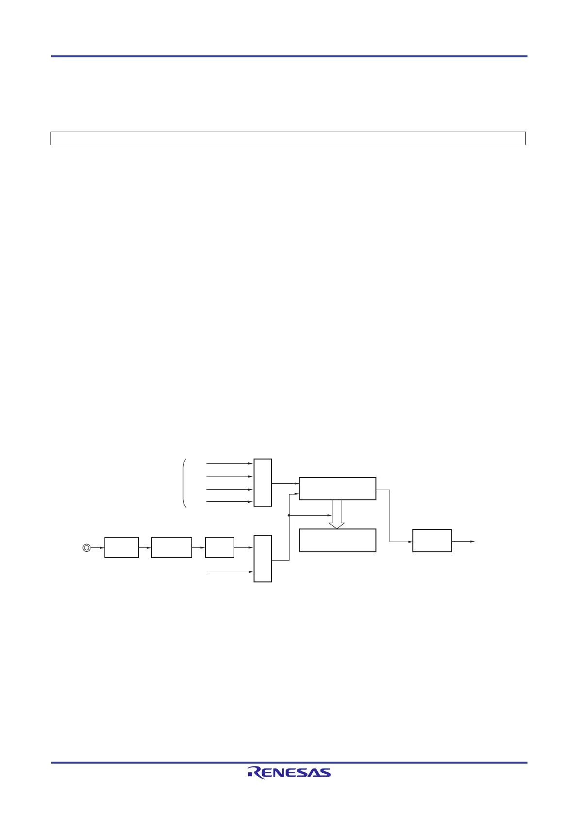
Figure 6-55. Block Diagram of Operation as Input Pulse Interval Measurement
Remarks 1. m: Unit number (m = 0, 1), n: Channel number (n = 0 to 7)
2. Unit 1 is not provided in the Group A products.
Channels 7 to 4 of unit 1 are not provided in the Group B, C, and D products.
Interrupt signal
(INTTMmn)
Interrupt
controller
Clock selection
Trigger selection
Edge
detection
TSmn
Timer counter
register mn (TCRmn)
Timer data
register mn (TDRmn)
CKm2
CKm3
Operation clock
CKm0
CKm1
TImn pin
Noise
filter
NFEN1 and
NFEN2
registers
 Loading...


