RL78/F13, F14 CHAPTER 28 REGULATOR
R01UH0368EJ0210 Rev.2.10 1614
Dec 10, 2015
CHAPTER 28 REGULATOR
28.1 Regulator Overview
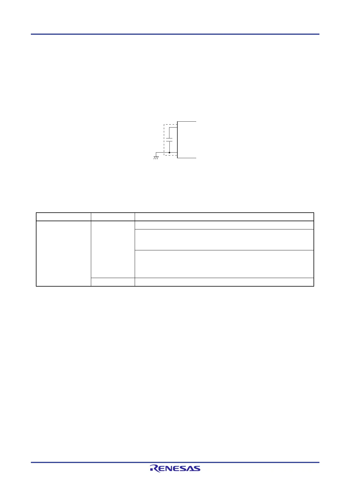
The RL78/F13 and RL78/F14 contain a circuit for operating the device with a constant voltage. At this time, in order to
stabilize the regulator output voltage, connect the REGC pin to V
SS via a capacitor (0.47 to 1
F). Also, use a capacitor with
good characteristics, since it is used to stabilize internal voltage.
Caution Keep the wiring length as short as possible for the broken-line part in the above figure.
For the regulator output voltage, see Table 28-1.
Table 28-1. Regulator Output Voltage Conditions
Mode Output Voltage Condition
High-speed main mode 1.86 V In STOP mode
When the high-speed system clock (fMX), the high-speed on-chip oscillator clock
(f
IH), and PLL clock (fPLL) are stopped during CPU operation with the
subsystem/low-speed on-chip oscillator clock select clock (f
SL)
When the high-speed system clock (fMX), the high-speed on-chip oscillator clock
(f
IH), and PLL clock (fPLL) are stopped during the HALT mode when the CPU
operation with the subsystem/low-speed on-chip oscillator clock select clock (f
SL)
has been set
2.1 V
Other than above (include during OCD mode)
Note
Note When it shifts to the subsystem/low-speed on-chip oscillator clock select clock operation or STOP mode during
the on-chip debugging, the regulator output voltage is kept at 2.1 V (not decline to 1.86 V).
REGC
V
SS

 Loading...


