RL78/F13, F14 CHAPTER 6 TIMER ARRAY UNIT
R01UH0368EJ0210 Rev.2.10 452
Dec 10, 2015
6.3.6 Timer channel start register m (TSm)
The TSm register is a trigger register that is used to initialize timer count register mn (TCRmn) and start the counting
operation of each channel.
When a bit of this register is set to 1, the corresponding bit of timer channel enable status register m (TEm) is set to 1.
The TSmn, TSHm1, TSHm3 bits are immediately cleared when operation is enabled (TEmn, TEHm1, TEHm3 = 1), because
they are trigger bits.
The TSm register can be set by a 16-bit memory manipulation instruction.
Set the lower 8 bits of the TSm register with a 1-bit or 8-bit memory manipulation instruction with TSmL.
Reset signal generation clears this register to 0000H.
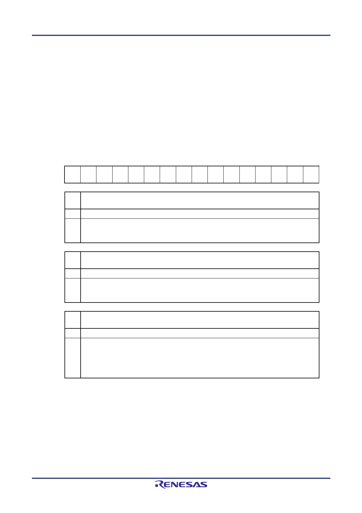
Figure 6-16. Format of Timer Channel Start Register m (TSm)
Address: F01B2H, F01B3H (TS0), F01F2H, F01F3H (TS1) After reset: 0000H R/W
Symbol 15 14 13 12 11 10 9 8 7 6 5 4 3 2 1 0
TSm 0 0 0 0
TSHm
3
0
TSHm
1
0
TSm
7
TSm
6
TSm
5
TSm
4
TSm
3
TSm
2
TSm
1
TSm
0
TSH
m3
Trigger to enable operation (start operation) of the higher 8-bit timer when channel 3 is in the 8-bit timer mode
0 No trigger operation
1
The TEHm3 bit is set to 1 and the count operation becomes enabled.
The TCRm3 register count operation start in the interval timer mode in the count operation enabled state
(see Table 6-6 in 6.5.2 Start timing of counter).
TSH
m1
Trigger to enable operation (start operation) of the higher 8-bit timer when channel 1 is in the 8-bit timer mode
0 No trigger operation
1
The TEHm1 bit is set to 1 and the count operation becomes enabled.
The TCRm1 register count operation start in the interval timer mode in the count operation enabled state
(see Table 6-6 in 6.5.2 Start timing of counter).
TSm
n
Operation enable (start) trigger of channel n
0 No trigger operation
1
The TEmn bit is set to 1 and the count operation becomes enabled.
The TCRmn register count operation start in the count operation enabled state varies depending on each
operation mode (see Table 6-6 in 6.5.2 Start timing of counter).
This bit is the trigger to enable operation (start operation) of the lower 8-bit timer for TSm1 and TSm3 when
channel 1 or 3 is in the 8-bit timer mode.
Cautions 1. Be sure to clear bits 15 to 12, 10, and 8 to “0”.
2. Be sure to clear TS1n (n = 7 to 4) to “0” in the Group B, C, and D products.
3. When switching from a function that does not use TImn pin input to one that does, the following
wait period is required from when timer mode register mn (TMRmn) is set until the TSmn
(TSHm1, TSHm3) bit is set to 1.
When the TImn pin noise filter is enabled (TNFENmn = 1): Four cycles of the operation clock
(f
MCK)
When the TImn pin noise filter is disabled (TNFENmn = 0): Two cycles of the operation clock
(f
MCK)
Remarks 1. When the TSm register is read, 0 is always read.
2. m: Unit number (m = 0, 1), n: Channel number (n = 0 to 7)
3. TS1n is not provided in the Group A products.
TS17 to TS14 are not provided in the Group B, C, and D products.

 Loading...


