RL78/F13, F14 CHAPTER 7 TIMER RJ
R01UH0368EJ0210 Rev.2.10 558
Dec 10, 2015
7.4.3 Pulse Output Mode
In this mode, the counter is decremented by the count source selected by bits TCK0 to TCK2 in the TRJMR0 register,
and the output level of pins TRJIO0 and TRJO0 pin is inverted each time an underflow occurs.
In pulse output mode, the count value is decremented by 1 each time the count source is input. When the count value
reaches 0000H and the next count source is input, an underflow occurs and an interrupt request is generated.
In addition, a pulse can be output from pins TRJIO0 and TRJO0. The output level is inverted each time an underflow
occurs. The pulse output from the TRJO0 pin can be stopped by the TOENA bit in the TRJIOC0 register.
Also, the output level can be selected by the TEDGSEL bit in the TRJIOC0 register.
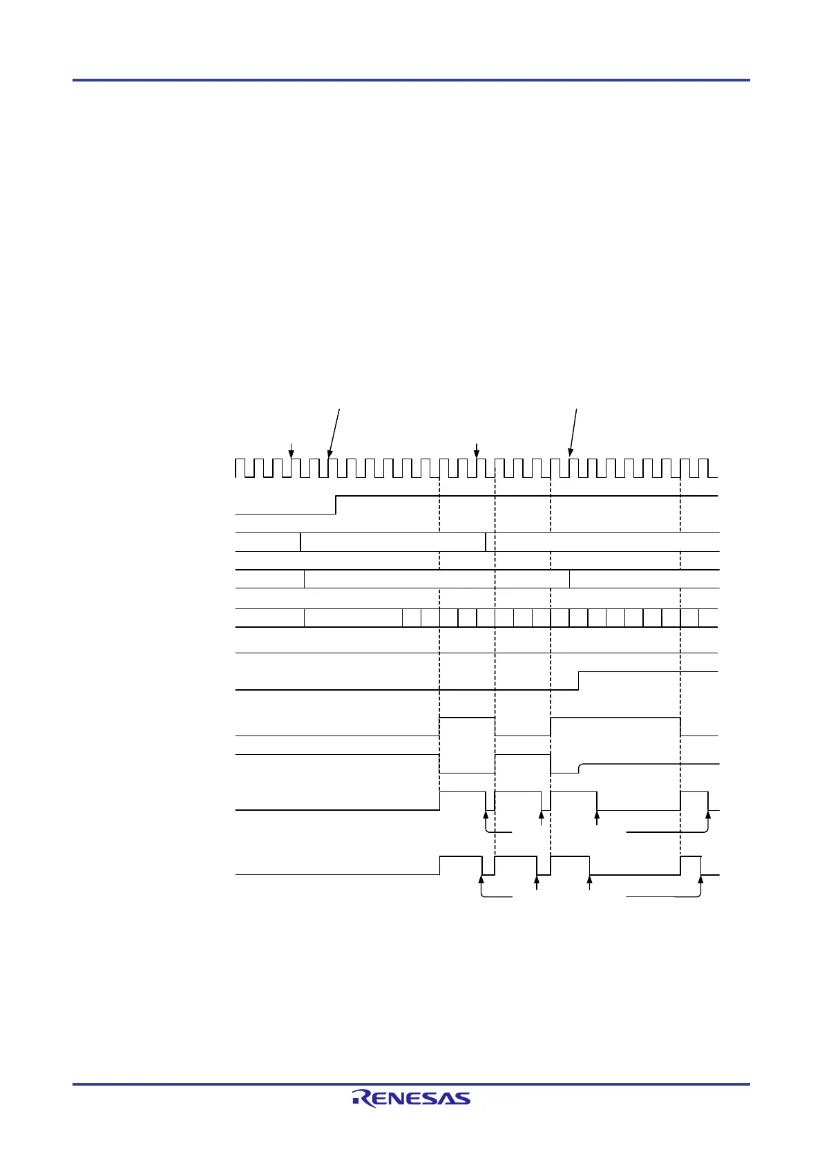
Figure 7-13 shows the Operation Example in Pulse Output Mode.
Caution The 20-pin products do not have TRJIO0 and TRJO0 pins. Thus, the pulse output mode cannot be used.
Figure 7-13. Operation Example in Pulse Output Mode
Write 0002H to
TRJ0 register by
a program
Write 0004H to
TRJ0 register by a
program
0002HFFFFH 0004H
0
Timer RJ0 counter
Set to 0 by a program
0002HFFFFH 0004H
Note 1: The TRJIO0 pin becomes high impedance by output enable control on the port selected as the TRJIO0 function.
TEDGSEL bit in
TRJIOC0 register
Count source
TSTART bit in
TRJCR0 register
TRJ0 register
Reload register
Port mode register (PMxx) bit
corresponding to port multiplexed
with TRJIO0 function
TRJO0 pin output
TRJIO0 pin output
TUNDF bit in
TRJCR0 register
High-impedance
state (Note 1)
Write 1 to TSTART bit in TRJCR0 register
by a program
0001H 0000H 0002H0001H 0000H 0002H0001H 0000H 0002H0001H 0004H 0003H0002H 0001H0000H 0004H 0003H
0002HFFFFH
Write 1 to port mode register (PMxx)
bit corresponding to port multiplexed
with TRJIO0 function
Acknowledgement of
an interrupt request
IF bit in
INTC register

 Loading...


