RL78/F13, F14 CHAPTER 9 REAL-TIME CLOCK
R01UH0368EJ0210 Rev.2.10 666
Dec 10, 2015
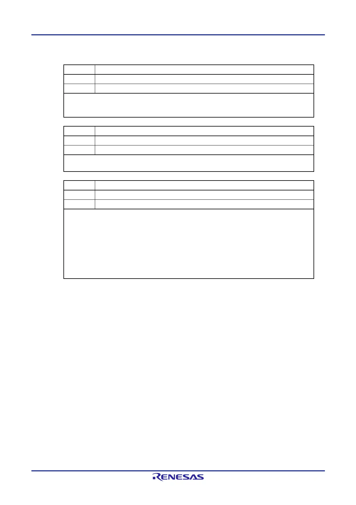
Figure 9-8. Format of Real-time Clock Control Register 1 (RTCC1) (2/2)
RIFG Constant-period interrupt status flag
0 Fixed-cycle interrupt is not generated.
1 Fixed-cycle interrupt is generated.
This flag indicates the status of generation of the fixed-cycle interrupt. When the fixed-cycle interrupt is generated,
it is set to “1”.
This flag is cleared when “0” is written to it. Writing “1” to it is invalid.
RWST Wait status flag of real-time clock
0 Counter is operating.
1 Mode to read or write counter value
This status flag indicates whether the setting of the RWAIT bit is valid.
Before reading or writing the counter value, confirm that the value of this flag is 1.
RWAIT Wait control of real-time clock
0 Sets counter operation.
1 Stops SEC to YEAR counters. Mode to read or write counter value
This bit controls the operation of the counter.
Be sure to write “1” to it to read or write the counter value.
As the internal counter (16 bits) is continuing to run, complete reading or writing within one second and turn back to
0.
When RWAIT = 1, it takes up to 1 operating clock (f
RTC) until the counter value can be read or written (RWST = 1).
Notes 1, 2
When the internal counter (16 bits) overflowed while RWAIT = 1, it keeps the event of overflow until RWAIT = 0,
then counts up.
However, when it wrote a value to second count register, it will not keep the overflow event.
Notes 1. When setting RWAIT=1 during 1 operating clock (fRTC) after setting RTCE=1, it may take
two clock time of the operation clock(fRTC) until RWST bit becomes “1”.
Notes 2. When setting RWAIT=1 during 1 operating clock (f
RTC) after returning from a stand-by
(HALT mode, STOP mode, SNOOZE mode), it may take two clock time of the operation
clock(f
RTC) until RWST bit becomes “1”.
Caution If writing is performed to the RTCC1 register with a 1-bit manipulation instruction, the RIFG
flag and WAFG flag may be cleared. Therefore, to perform writing to the RTCC1 register, be
sure to use an 8-bit manipulation instruction. To prevent the RIFG flag and WAFG flag from
being cleared during writing, disable writing by setting 1 to the corresponding bit. If the RIFG
flag and WAFG flag are not used and the value may be changed, the RTCC1 register may be
written by using a 1-bit manipulation instruction.
Remarks 1. Fixed-cycle interrupts and alarm match interrupts use the same interrupt source (INTRTC). When
using these two types of interrupts at the same time, which interrupt occurred can be judged by
checking the fixed-cycle interrupt status flag (RIFG) and the alarm detection status flag (WAFG)
upon INTRTC occurrence.
2. If writing is performed to the second count register (SEC), the internal counter (16 bits) is cleared.
<R>
<R>

 Loading...


