RL78/F13, F14 CHAPTER 17 LIN/UART MODULE (RLIN3)
R01UH0368EJ0210 Rev.2.10 1236
Dec 10, 2015
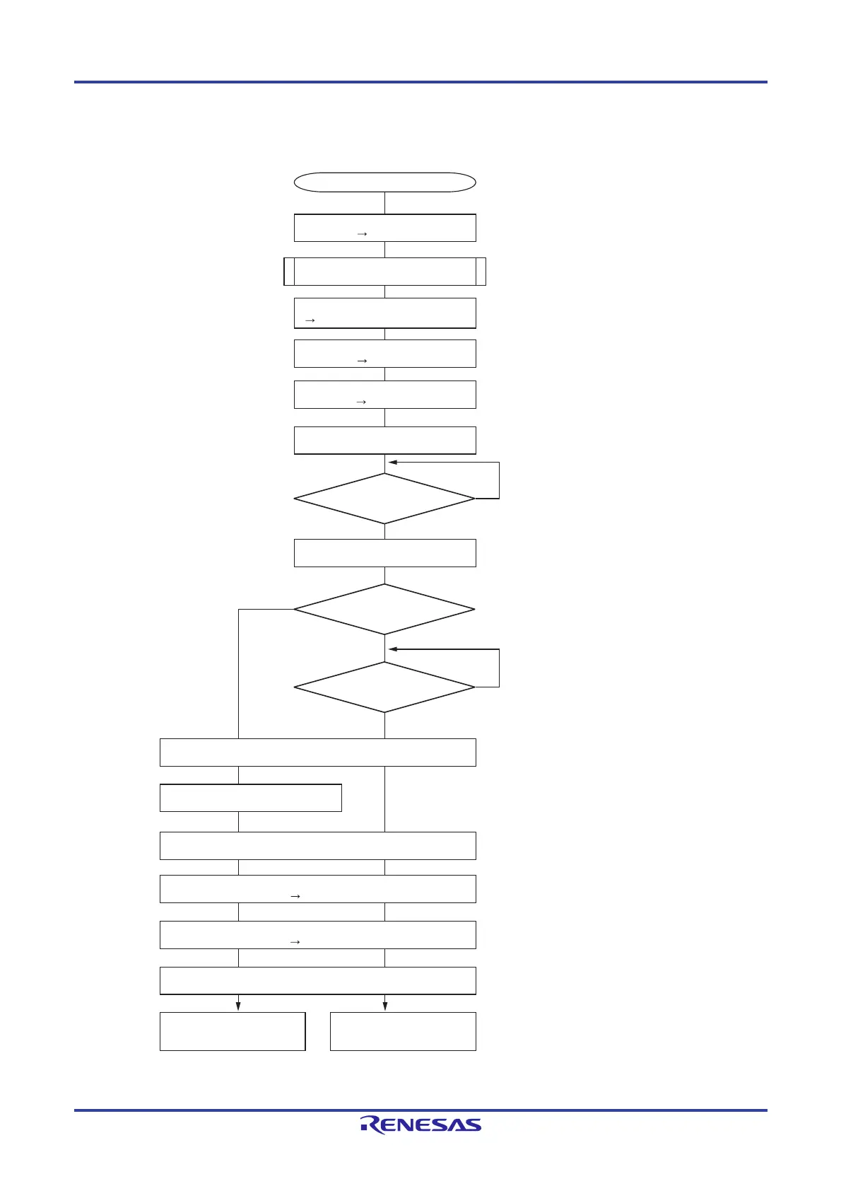
Figure 17-33. Flowchart of SNOOZE Mode Operation
(returning to normal operation upon successful reception; UWC = 1, URDCC = 0)
Remark (1) to (11) in Figure 17-33 correspond to (1) to (11) in Figure 17-32.
Setting start
Cancels LIN reset mode.
LBFCn, LUORn1: Set communication.
LWBRn, LBRPn: Set baud rate.
No
Y
es
(7)
Cause transition to SNOOZE mode.
(6)
Clock request signal level goes high to
request clock generator to supply f
CLK
(high-speed on-chip oscillator clock);
clock supply to LIN/UART module is started
after oscillation precision stabilization time.
(5)
Cause transition to STOP mode.
Stops f
CLK
supply to LIN/UART module.
(4)
Enables reception.
(3)
Turns on SNOOZE mode.
(2)
Makes transition to LIN reset mode.
(1)
(10)
(9)
Read LESTn register.
Makes transition to LIN reset mode.
n = 0, 1
(11)
Write 0 to UWC bit.
Clock request signal level goes low.
(8)
Yes
Successful reception interrupt occurrence
indicated by INTLINnRVC?
No
Error interrupt occurrence
indicated by INTLINnSTA?
No
Yes
LRXDn edge detected?
Error processing
LIN/UART module (UART mode)
starts normal operation.
Normal processing
LIN/UART module (UART mode)
starts normal operation.
Write 0 to OM0 bit.
Set LUSCn register.
Write 1 to OM0 bit.
Write 1 to UROE bit.
Write 0 to UROE bit.
Write 0 to OM0 bit.
OMM0 = 0
UROE = 0
UROE = 1
OMM0 = 1
UWC = 1, USEC = 0, URDCC = 0
OMM0 = 0
Supplies clock to start UART reception.
Read LURDRn register.
Returns from SNOOZE mode to normal operation.

 Loading...


