RL78/F13, F14 CHAPTER 23 STANDBY FUNCTION
R01UH0368EJ0210 Rev.2.10 1535
Dec 10, 2015
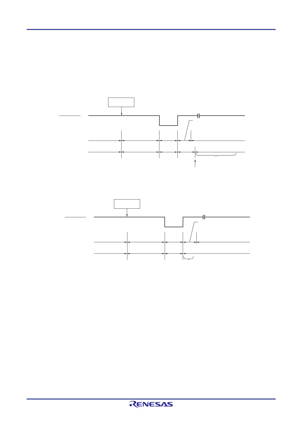
(b) Release by reset signal generation
When the reset signal is generated, STOP mode is released, and then, as in the case with a normal reset operation,
the program is executed after branching to the reset vector address.
Figure 23-7. STOP Mode Release by Reset
(1) When high-speed system clock is used as CPU clock
(2) When high-speed on-chip oscillator clock is used as CPU clock
Note For the reset processing time, see CHAPTER 25 POWER-ON-RESET CIRCUIT.
STOP
instruction
Reset signal
High-speed
system clock
(X1 oscillation)
Normal operation
(high-speed
system clock)
STOP mode
Reset
period
Normal operation
(high-speed on-chip
oscillator clock)
Oscillates
Oscillation
stopped
Oscillates
Status of CPU
Oscillation stabilization time
(Check by using OSTC register)
Oscillation
stopped
Starting X1 oscillation is
specified by software.
Oscillation stopped
Reset processing
Note
STOP
instruction
Reset signal
High-speed on-chip
oscillator clock
Normal operation
(high-speed on-chip
oscillator clock)
STOP mode
Reset
period
Normal operation
(high-speed on-chip
oscillator clock)
Oscillates
Oscillation
stopped
Status of CPU
Oscillates
Oscillation stopped
Wait for oscillation
accuracy stabilization
Reset processing
Note

 Loading...


