RL78/F13, F14 CHAPTER 6 TIMER ARRAY UNIT
R01UH0368EJ0210 Rev.2.10 465
Dec 10, 2015
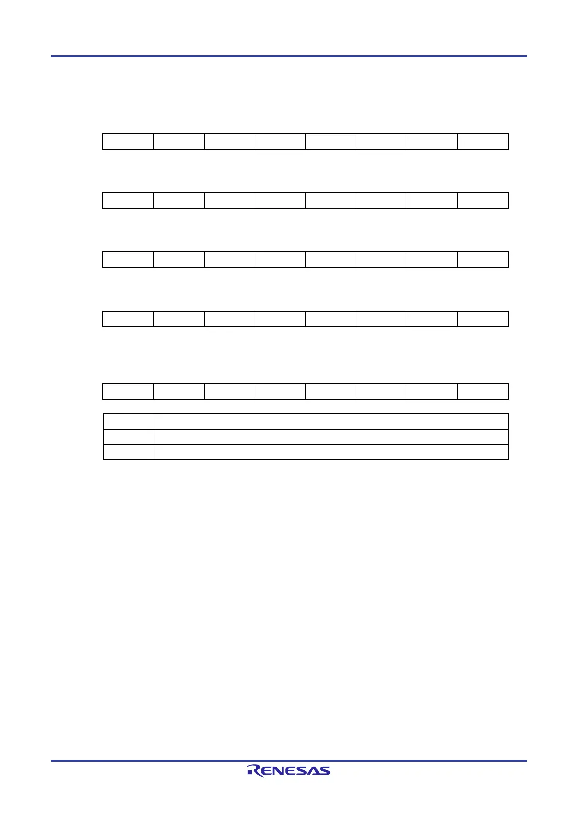
Figure 6-26. Format of Port Mode Registers 1, 3, 4, 7, 12 (PM1, PM3, PM4, PM7, PM12) (100-pin products)
Address: FFF21H After reset: FFH R/W
Symbol 7 6 5 4 3 2 1 0
PM1 PM17 PM16 PM15 PM14 PM13 PM12 PM11 PM10
Address: FFF23H After reset: FFH R/W
Symbol 7 6 5 4 3 2 1 0
PM3 1 1 1 PM34 PM33 PM32 PM31 PM30
Address: FFF24H After reset: FFH R/W
Symbol 7 6 5 4 3 2 1 0
PM4 PM47 PM46 PM45 PM44 PM43 PM42 PM41 PM40
Address: FFF27H After reset: FFH R/W
Symbol 7 6 5 4 3 2 1 0
PM7 PM77 PM76 PM75 PM74 PM73 PM72 PM71 PM70
Address: FFF2CH After reset: FFH R/W
Symbol 7 6 5 4 3 2 1 0
PM12 PM127 PM126 PM125 1 1 1 1 PM120
PMmn Pmn pin I/O mode selection (m = 1, 3, 4, 7, 12; n = 0 to 7)
0 Output mode (output buffer on)
1 Input mode (output buffer off)
Remark The figure shown above presents the format of port mode registers 1, 3, 4, 7, and 12 of the 100-pin products.
The format of the port mode register of other products, see CHAPTER 4 PORT FUNCTIONS.

 Loading...


