RL78/F13, F14 CHAPTER 15 SERIAL ARRAY UNIT
R01UH0368EJ0210 Rev.2.10 808
Dec 10, 2015
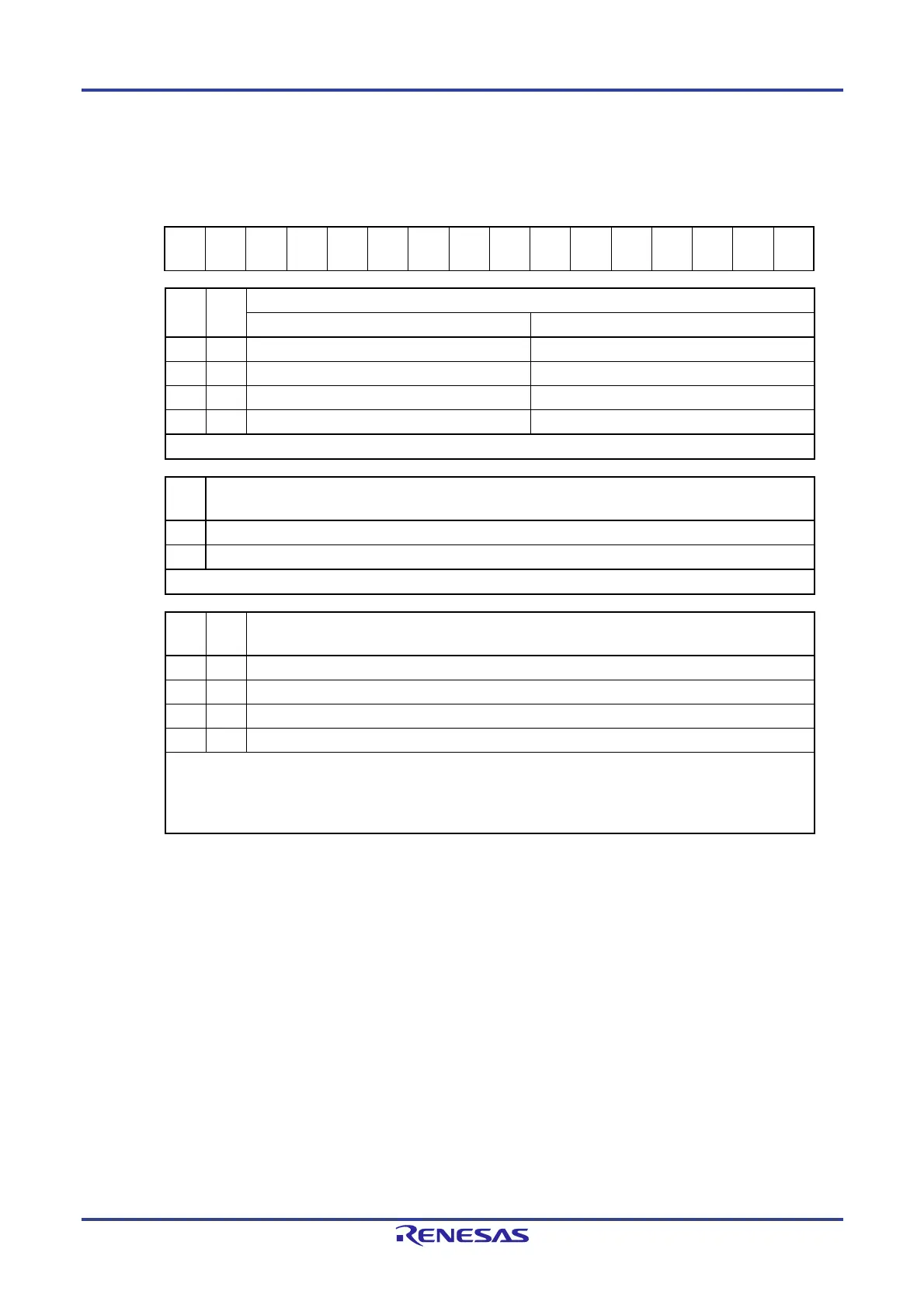
Figure 15-7. Format of Serial Communication Operation Setting Register mn (SCRmn) (2/3)
Address: F010CH, F0110DH (SCR00), F010EH, F010FH (SCR01), After reset: 0087H R/W
F014CH, F014DH (SCR10), F014EH, F014FH (SCR11)
Symbol 15 14 13 12 11 10 9 8 7 6 5 4 3 2 1 0
SCRmn
TXE
mn
RXE
mn
DAP
mn
CKP
mn
0 0
PTC
mn1
PTC
mn0
DIR
mn
0
SLC
mn1
SLC
mn0
DLS
mn3
DLS
mn2
DLS
mn1
DLS
mn0
PTC
mn1
PTC
mn0
Setting of parity bit in UART mode
Transmission Reception
0 0 Does not output the parity bit. Receives without parity
0 1 Outputs 0 parity
Note
. No parity judgment
1 0 Outputs even parity. Judged as even parity.
1 1 Outputs odd parity. Judges as odd parity.
Be sure to set PTCmn1, PTCmn0 = 0, 0 in the CSI mode and simplified I
2
C mode.
DIR
mn
Selection of data transfer sequence in CSI and UART modes
0 Inputs/outputs data with MSB first.
1 Inputs/outputs data with LSB first.
Be sure to clear DIRmn = 0 in the simplified I
2
C mode.
SLCm
n1
SLC
mn0
Setting of stop bit in UART mode
0 0 No stop bit
0 1 Stop bit length = 1 bit
1 0 Stop bit length = 2 bits (mn = 00, 10 only)
1 1 Setting prohibited
When the transfer end interrupt is selected, the interrupt is generated when all stop bits have been completely
transferred.
Set 1 bit (SLCmn1, SLCmn0 = 0, 1) during UART reception and in the simplified I
2
C mode.
Set no stop bit (SLCmn1, SLCmn0 = 0, 0) in the CSI mode.
Note "0" is always added regardless of the contents of data.
Caution Be sure to clear bits 6, 10, and 11 to 0.
Remark m: Unit number (m = 0, 1), n: Channel number (n = 0, 1), p: CSI number (p = 00, 01, 10, 11)

 Loading...


