RL78/F13, F14 CHAPTER 15 SERIAL ARRAY UNIT
R01UH0368EJ0210 Rev.2.10 961
Dec 10, 2015
(1) Register setting
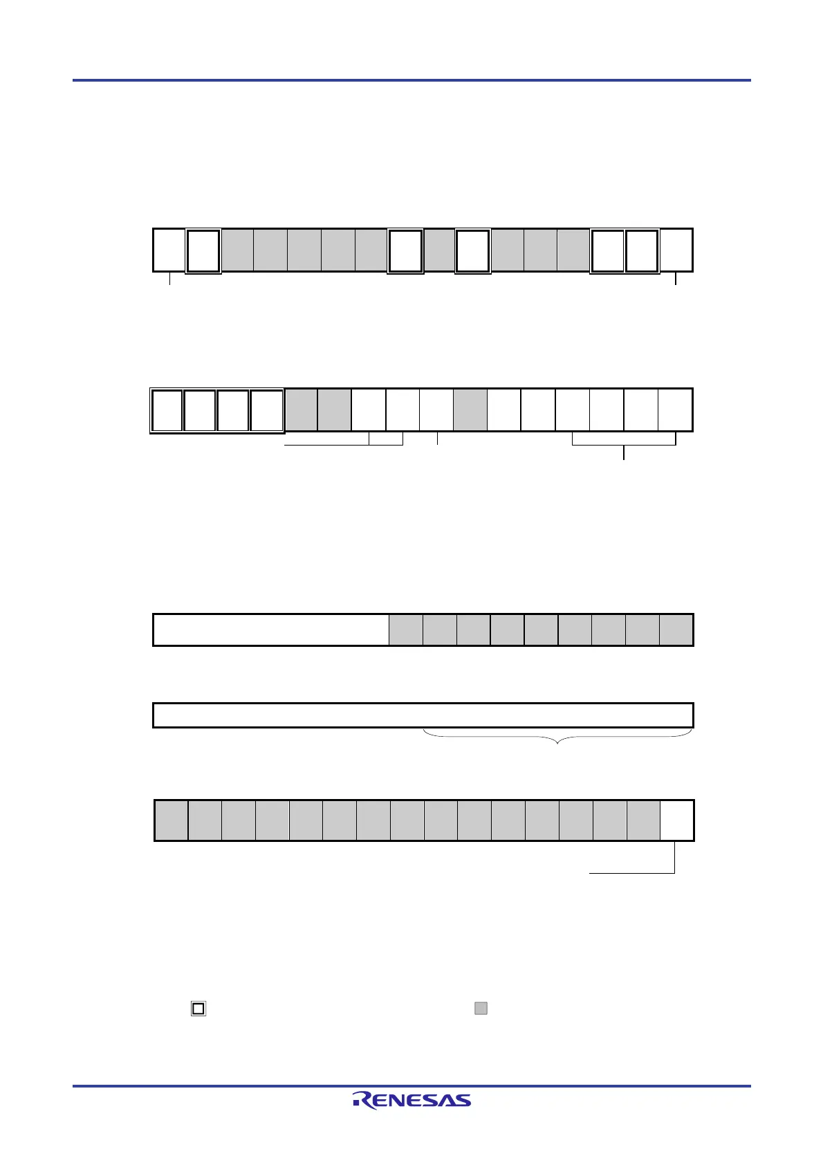
Figure 15-121. Example of Contents of Registers for UART Transmission of UART
(UART0, UART1) (1/2)
(a) Serial mode register mn (SMRmn)
15 14 13 12 11 10 9 8 7 6 5 4 3 2 1 0
SMRmn
CKSmn
0/1
CCSmn
0
0
0
0
0
0
STSmn
0
0
SISmn0
0
1
0
0
MDmn2
0
MDmn1
1
MDmn0
0/1
Operation clock (fMCK) of channel n
0: Prescaler output clock CKm0 set by the SPSm register
1: Prescaler output clock CKm1 set by the SPSm register
Interrupt source of channel n
0: Transfer end interrupt
1: Buffer empty interrupt
(b) Serial communication operation setting register mn (SCRmn)
15 14 13 12 11 10 9 8 7 6 5 4 3 2 1 0
SCRmn
TXEmn
1
RXEmn
0
DAPmn
0
CKPmn
0
0
0
PTCmn1
0/1
PTCmn0
0/1
DIRmn
0/1
0
SLCmn1
0/1
SLCmn0
0/1
DLSmn3
0/1
DLSmn2
0/1
DLSmn1
0/1
DLSmn0
0/1
Selection of data
transfer sequence
0: Inputs/outputs
data with MSB first
1: Inputs/outputs
data with LSB first.
Setting of stop bit
01B: Appending 1
bit
10B: Appending 2
bits
Setting of parity bit
00B: No parity
01B: Appending 0 parity
10B: Appending Even parity
11B: Appending Odd parity
Setting of data length
0110B: 7 bits
0111B: 8 bits
1000B: 9 bits
1111B: 10 bits
(c) Serial data register mn (SDRmn)
(1) When operation is stopped (SEmn = 0)
15 14 13 12 11 10 9 8 7 6 5 4 3 2 1 0
SDRmn
Baud rate setting
0
0
0
0
0
0
0
0
0
(2) When operation is in progress (SEmn = 1) (Lower 8 bits: SDRmnL)
15 14 13 12 11 10 9 8 7 6 5 4 3 2 1 0
SDRmn
Transmit data setting
(d) Serial output level register m (SOLm) … Sets only the bits of the target channel.
15 14 13 12 11 10 9 8 7 6 5 4 3 2 1 0
SOLm
0
0
0
0
0
0
0
0
0
0
0
0
0
0
0
SOLm0
0/1
0: Forward (normal) transmission
1: Reverse transmission
Note Before transmission is started, be sure to set to 1 when the SOLmn bit of the target channel is set to 0, and
set to 0 when the SOLmn bit of the target channel is set to 1. The value varies depending on the
communication data during communication operation.
Remarks 1. m: Unit number (m = 0, 1), n: Channel number (n = 0), mn = 00, 10
2. : Setting is fixed in the UART transmission mode, : Setting disabled (set to the initial value)
×: Bit that cannot be used in this mode (set to the initial value when not used in any mode)
0/1: Set to 0 or 1 depending on the usage of the user
SDRmnL
 Loading...


