R5905948 /12 Event Master Devices 189
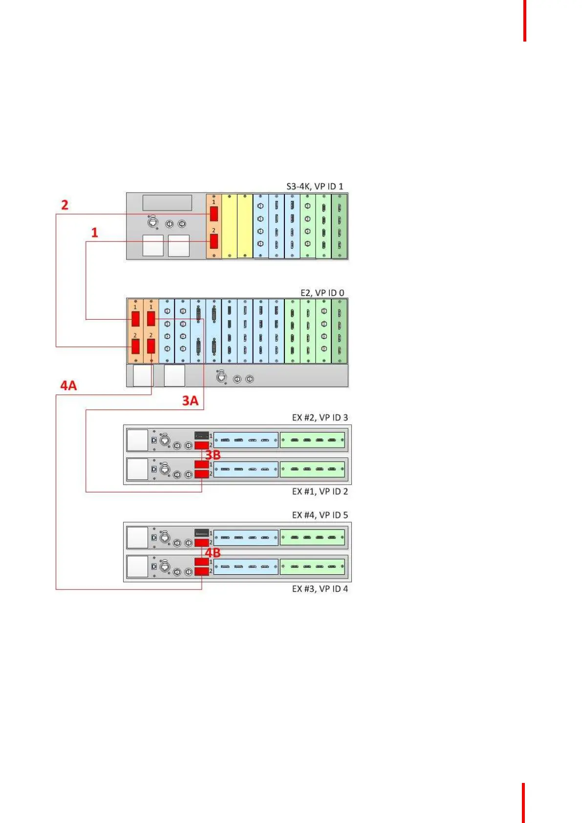
Connect the Link cables provided with each unit between the Link connectors as follows:
• E2 VP ID 0, Link Card slot 1, Link 1 >> S3 VP ID 1, Link Card slot 1, Link 2 [1]
• E2 VP ID 0, Link Card slot 1, Link 2 >> S3 VP ID 1, Link Card slot 1, Link 1 [2]
• E2 VP ID 0, Link Card slot 2, Link 1 >> EX VP ID 2, Link 2 [3A]
• EX VP ID 2, Link 1 >> EX VP ID 3, Link 2 [3B]
• E2 VP ID 0, Link Card slot 2, Link 2 >> EX VP ID 4, Link 2 [4A]
• EX VP ID 4, Link 1 >> EX VP ID 5, Link 2 [4B]
See Image 6-54 for an example of the cabling between an E2 unit, an S3-4K unit, and four EX units.
Image 6-54: Cabling between an E2 unit, an S3–4K unit, and four EX units
Event Master Configuration for Linking an E2, an S3-4K, and four EX Units
1. Start the Event Master Toolset version 4.1 or higher.
2. Make sure that the E2, the S3–4K, and the EX units are discovered on the network and that they have different
Unit IDs.
3. Drop the E2 in the GUI.
All linked frames will appear below the E2 as grayed-out representations of each linked frame.
4. Click the "+Add as Slave" button on the S3–4K.
5. Once the S3–4K is done synchronizing with the master, you may next add the EX frames as slaves.
EM GUI orientation