EasyManuals Logo

Benelli TNT125 Service Manual

Benelli TNT125
485 pages
To Next Page IconTo Next Page
To Previous Page IconTo Previous Page
Page #272 background imageLoading...
Page #272 background image
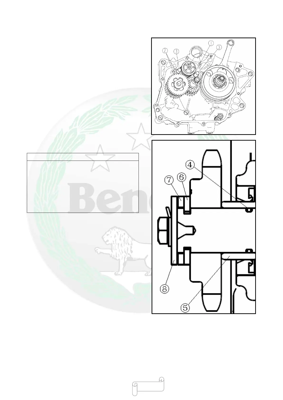
Installng Drive System
Install
Auxiliary shaft component
○Primary shaft component
○Shift drum component
Shift fork of primary shaft
S
hift fork of auxiliary shaft
S
hift fork shaft
O
ring seal Φ14×Φ1.8
O
il seal bushing
Roller sprocket
○Mounting plate of drive sprocket
Sprocket cover plate
A
uxiliary shaft cover plate
Locking washer
Bolt 12N•m Apply locking agent
N
ote
When installing the shift forks of primary shaft and
auxiliary shaft, ensure that the ribbed side of shift
fork
is opposite to the right crankcase of engine;
bend the flange A
a
E A on the locking washer to the
surface of hexagon head of bolt after ensuring that
the bolt of shift fork in the travel slot of shift drum is
tightened.
- 269 -

Table of Contents

Questions and Answers:

Question and Answer IconNeed help?

Do you have a question about the Benelli TNT125 and is the answer not in the manual?

Benelli TNT125 Specifications

General IconGeneral
Displacement125 cc
Transmission5-speed
Fuel SystemEFI
Fuel Capacity7.2 liters
Seat Height780 mm
Dry Weight116 kg
Bore x Stroke54 mm x 54.5 mm
Starting SystemElectric
Wheelbase1215 mm
Engine TypeSingle cylinder, 4-stroke, air-cooled
Front SuspensionUpside-down fork
Front BrakeSingle disc
Rear BrakeSingle disc
Front Tire120/70-12
Rear Tire130/70-12
Max Power8.2 kW (11.1 Cv) @ 9500 rpm
Rear SuspensionSwing arm with lateral shock absorber with adjustable spring preload

Related product manuals