EasyManuals Logo

Benelli TNT125 Service Manual

Benelli TNT125
485 pages
To Next Page IconTo Next Page
To Previous Page IconTo Previous Page
Page #358 background imageLoading...
Page #358 background image
Put the installing shaft [A] into the frame from the left
side.
●Lock the swing arm installing shaft nut [A].
Locking torque of swing arm installing shaft nut:
108 N·m
Install it in reverse order of disassembly (see th
e
c
orresponding chapters).
Disassembling Swing Arm Bushing
Disassemble:
Rear swing arm (see “Disassembling Rear Swing
Arm”),
Damper [A]
Middle shaft sleeve [B]
Checking Damper
Note
Do not remove the damper, otherwise it may be
damaged.
●Check the damper [A] installed inside the swing arm.
If there is any abnormal wear on the damper or
damage to the cushion rubber, please replace it as a
whole!
Checking Chain Guard
See “Regular Maintenance”—“Checking Wear of Chain Guide”
.
- 355 -

Table of Contents

Questions and Answers:

Question and Answer IconNeed help?

Do you have a question about the Benelli TNT125 and is the answer not in the manual?
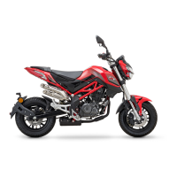
Benelli TNT125 Specifications

General IconGeneral
Displacement125 cc
Transmission5-speed
Fuel SystemEFI
Fuel Capacity7.2 liters
Seat Height780 mm
Dry Weight116 kg
Bore x Stroke54 mm x 54.5 mm
Starting SystemElectric
Wheelbase1215 mm
Engine TypeSingle cylinder, 4-stroke, air-cooled
Front SuspensionUpside-down fork
Front BrakeSingle disc
Rear BrakeSingle disc
Front Tire120/70-12
Rear Tire130/70-12
Max Power8.2 kW (11.1 Cv) @ 9500 rpm
Rear SuspensionSwing arm with lateral shock absorber with adjustable spring preload

Related product manuals