Home
Benelli
Motorcycle
TNT125
Page 74 (Checking Wear of Chain Guide)
Benelli TNT125 - Checking Wear of Chain Guide
485 pages
Manual
Save Page as PDF
To Next Page
To Next Page
To Previous Page
To Previous Page
Loading...
Chec
king
W
ear
of Chain Guide
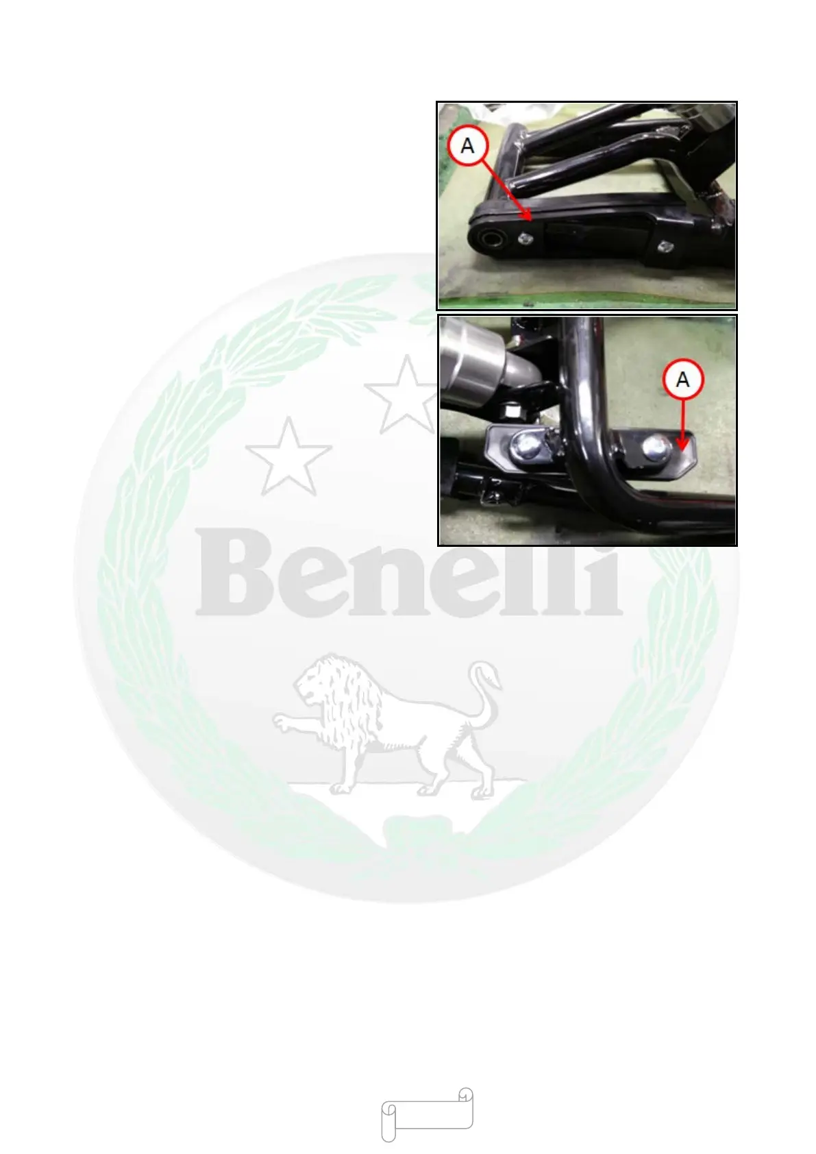
●Remove
the
swing
arm
(see
“Disassembling
Rear
Swing
Arm” in “Suspensi
on Sy
stem”).
●V
isually
checking the chain gui
de [A].
★
If there i
s abnormal w
ear or damage in
the chai
n
guide, it m
ust be repl
aced.
-
71 -
73
75
Table of Contents
Main Page
Exhaust Emission Control Information
4
Table of Contents
6
Preface
22
Chapter I Basic Information
23
Notes before Maintenance
24
Battery Grounding
24
Sharp Edge of Part
24
Solvent
24
Cleaning Motorcycle before Disassembly
25
Collecting and Cleaning Removed Part
25
Storing Removed Part
25
Check
25
Replacement Part
26
Assembly Order
26
Fastening Order
26
Tightening Torque
26
Force
27
Gasket and O-Ring Seal
27
Mould Closing Glue and Threaded Fastening Glue
27
Press Fitting
27
Ball Bearing and Needle Bearing
29
Oil Seal and Grease Oil Seal
29
Circlip and Cotter Pin
30
Lubrication
30
Rotation Direction of Engine
30
Wire
30
Cable Connector Check
31
Disconnection
31
Check
31
Check
32
Cable Arrangement
33
Tool
33
Model Information
34
China
34
Europe
36
Non-Europe
38
Basic Specification
41
General Technical Parameter
43
Unit Conversion Table
46
Chapter II Regular Maintenance
47
Regular Maintenance Table
49
Torque and Locking Agent
51
Main Locking Torque Specifications
51
Nut, Bolt, Screw Fastening Torque and Relative Parameters
55
Technical Parameters
56
Special Tools
58
Regular Maintenance Procedures
59
Electronic Fuel Injection System (EFI)
59
Checking Throttle Control System
59
Checking Idle Speed
60
Checking Fuel Hose (Fuel Leakage, Hose Break and Hose Installation Situations)
61
Checking Fuel Evaporation and Recovery System (Chinese, European and US Models)
62
Engine Cylinder Head and Cylinder Head Cover
64
Checking Valve Clearance
64
Adjusting Valve Clearance
66
Clutch
67
Checking Whether Clutch Control System Is Normal
67
Checking Free Travel of Clutch Handle
67
Wheel/Tire
68
Checking Tire Pressure
68
Checking Whether Wheel/Tire Is Broken
68
Checking Wear Situations of Thread
69
Checking Whether Wheel Bearing Is Damaged
69
Final Drive Mechanism
71
Checking Lubrication State of Drive Chain
71
Checking Whether Drive Chain Is Loose
71
Adjusting Slackness of Drive Chain
72
Checking Wheel Alignment
73
Checking Wear of Drive Chain
73
Checking Wear of Chain Guide
74
Brake
75
Check Whether Brake Hose and Brake Pipe Are Damaged and Their Installation States
75
Free Travel of Front Brake
75
Free Travel of Rear Brake
75
Checking Brake
76
Checking Brake Fluid Level
76
Checking Wear of Brake Pad
79
Checking Brake Light Switch
79
Suspension System
80
Checking Front Fork/Rear Shock Absorber
80
Check for Oil Leakage of Front Fork Shock Absorber
80
Check for Oil Leakage of Rear Shock Absorber
81
Steering System
82
Checking Steering Clearance
82
Adjusting Tightness of Steering Seat
82
Applying Lubricant to Steering Column Bearing
84
Electrical System
85
Checking Light and Switch
85
Checking Accuracy of Headlight
90
Checking Emergency Flameout Switch
91
Others
92
Applying Lubricant to Frame Parts
92
Check Tightness of Bolt, Nut and Fastener
95
Replacement Part
97
Replacing Air Filter Element
97
Replacing Fuel Pipe
99
Replacing Oil
101
Replacing Brake Hose and Brake Pipe
103
Replacing Brake Fluid
106
Replacing Rubber Parts of Master Cylinder
110
Replacing Rubber Parts of Calipers
112
Replacing Spark Plug
120
Chapter III Electronic Fuel Injection System (EFI)
121
Introduction to EFI
125
EFI System
126
EFI Part Position
128
Technical Parameters
134
Fuel Tank
136
Exploded View of Fuel Tank
136
Evaporative Emission Recovery System of Fuel
138
Disassembly of Fuel Tank
139
Check
141
Installatation of Fuel Tank
143
Notes for EFI Overhaul
144
Ecu
146
Engine Controller (MT05.2ECU)
146
ECU Appearance
146
ECU Disassembly
146
ECU Installation
147
Notes for ECU
147
ECU Power Supply Requirements
147
ECU Temperature Requirements
148
Fuel Pump
149
Working of Fuel Pump
149
Appearance of Fuel Pump
150
Composition of Fuel Pump
151
Label and Mark of Fuel Pump
151
Working Environment of Fuel Pump
152
Fuel Pump Maintenance Process
152
Safety Protection
152
Fault Diagnosis of Fuel Pump Assembly
153
Disassembly of Fuel Pump Assembly
153
Installation of Fuel Pump Assembly
154
Fuel Pressure Release Process
154
Fuel Leakage Check Process
155
Notes for Use
155
Throttle Body
157
Working Principle of Throttle Body
157
Appearance of Throttle Body
157
Technical Parameters
157
Throttle Body
158
Throttle Position Sensor
158
Air Control Valve of Idle Speed
158
Working Environment of Throttle
158
Disassembly of Throttle
158
Cleaning Method of Throttle
158
Installation of Throttle
158
Precautions for Installation of Throttle
158
Notes for Use of Throttle
159
Idle Speed Stepper Motor
159
Working Principle of Idle Speed Stepper Motor
159
Appearance of Idle Speed Stepper Motor
159
Definition of Pin
160
Characteristic Parameter
160
Fault Determination of Idle Speed Stepper Motor
160
Circuit Inspection of Idle Speed Stepper Motor
161
Cleaning
161
Resetting of Idle Speed Stepper Motor
161
Fuel Injector
162
Working Principle of Fuel Injector
162
Appearance of Fuel Injector
162
Sealing Ring of Fuel Injector
163
O-Ring Seal Connected to Oil Rail or Oil Injection Cap
163
O-Ring Seal Connected to Intake Pipe End
163
Recommended Lubricant
163
Overvoltage Impact of Fuel Injector
163
Temperature Range of Fuel Injector
164
Fuel Contaminants of Fuel Injector
164
Fuel Injector Harness Arrangement
164
Notes for Use of Fuel Injector
164
Requirements for Installation of Fuel Injector
165
Replacement Method of Fuel Injector
166
Fuel Injector Replaceability
167
Blocking of Fuel Injector
167
General Failure Mode and Prevention and Solving Measures in Using Process
168
Intake Pressure Sensor
169
Working Principle of Intake Pressure Sensor
169
Appearance of Intake Pressure Sensor
169
Working Environment
169
Storage Environment
169
Electric Environment
169
Pin Definition
170
Position
170
Cleaning
170
Fault Determination
170
Oxygen Sensor
171
Working Principle of Oxygen Sensor
171
Appearance of Oxygen Sensor
171
Technical Parameters
171
Installation Requirements
171
Oxygen Sensor Pin Definition
172
Fault Determination
172
Characteristic Curve
173
Requirements for Fuel Quality
173
Temperature Sensor of Engine Cylinder Head
174
Working Principle of Temperature Sensor of Engine Cylinder Head
174
Appearance of Temperature Sensor of Engine Cylinder Head
174
Working Environment
174
Electrical Environment
174
Fault Determination and Characteristic of Output Resistance
175
Canister Solenoid Valve (ECP)
176
Overview of Working Principles
176
Appearance
176
ECP Pin
176
Technical Parameters
177
Installation Requirements
177
Ignition Coil
178
Appearance of Ignition Coil
178
Fault Description
178
Fault Maintenance Diagnosis Method of EFI System
179
Diagnosis Directly Using the Flashing Fault Lamp at Instrument
179
Diagnosing Fault Using Diagnostic Apparatus
182
Common Troubleshooting Methods of Electronic Fuel Injection System
184
Maintenance Tool
184
Engine Working Data Flow Displayed by Diagnostic Apparatus
185
Step I
185
Simple Troubleshooting
187
Daily Use and Maintenance
187
Fault Phenomenon-Start Fault
188
Fault Phenomenon-Start Failure with Tempering
190
Fault Phenomenon-Instable Idle Speed
190
Fault Phenomenon-Too High or too Low Idle Speed
191
Target Idle Speed)
191
Fault Phenomenon-Instable Idle Speed with Deceleration and Flameout
192
Fault Phenomenon-Insufficient Power of Deceleration
192
Fault Phenomenon-Slight Burning Phenomenon
192
Fault Phenomenon-Fault Lamp Is On, but Fault Code Is Inconsistent with Fault
192
Fault Phenomenon-Extremely High Fuel Consumption
193
Fault Diagnosis Instructions for Delphi
194
Main Parameters of Engine
200
Lubrication System
201
Diagram of Lubrication System
201
Position of Fuel Pump
203
Preparation Information
205
Conventional Information
205
Technical Parameters
206
Torque Value
206
Special Tools
207
Troubleshooting
208
Oil Level Is too Low
208
Oil Pressure Is Low
208
There Is no Oil Pressure
208
Oil Pressure Is High
208
Oil Is Polluted
208
Oil Is Emulsified
208
Checking Fuel Pump
209
Cylinder Head / Distribution
210
Exploded View of Cylinder Head / Distribution
210
Preparation Information
211
Technical Parameters
211
Torque Value
211
Fault Diagnosis
212
Compression Pressure Is Low
212
The Sound of Cylinder Head Is Abnormal
212
Compression Pressure Is too High
212
Special Tools
213
Cylinder Head
214
Disassembling Cylinder Head
214
Checking Cylinder Head
217
Replacing Valve Guide
219
Finishing Valve Seat Ring
221
Cylinder Block / Piston
224
Exploded View of Cylinder Block / Piston
224
Exploded View of Crankshaft
225
Preparation Information
226
Technical Parameters
227
Torque Value
227
Fault Diagnosis
228
Compression Pressure Is Low
228
Compression Pressure Is High
228
Exhaust Pipe Is Emitting White Smoke
228
The Sound of Piston Is Abnormal
228
Special Tools
229
Cylinder Block
231
Disassembling
231
Check
231
Piston
231
Check
232
Installation
234
Installation of Cylinder Block
235
Crankshaft
235
Check
235
Sub-Assembly of Crankcase
237
Exploded View of Crankcase
237
Dismounting and Mounting Diagram of Crankcase Bearing
238
Preparation Information
239
Overview
239
Technical Parameters
239
Torque Value
239
Crankcase
240
Disassembling Crankcase
240
Checking Crankcase
240
Assembling Crankcase
242
Clutch
244
Exploded View of Left Cover
244
Exploded View of Clutch
245
Preparation Information
246
Conventional Information
246
Technical Parameters
247
Torque Value
247
Special Tools
248
Troubleshooting
249
Clutch Lever Is too Hard to Pull
249
Clutch Is Slipping When Accelerating
249
Clutch Does Not Disengage or Clutch Disengages Suddenly During the Running of Motorcycle
249
Right Cover
250
Disassembing Right Cover
250
Assembling Right Cover
250
Clutch
251
Disassembling Clutch
251
Assembling Clutch
252
Check
253
Subassembly of Cylinder Head Cover
255
Exploded View of Cylinder Head Cover
255
Preparation Information
256
Overview
256
Technical Parameters
256
Torque Valve
256
Cylinder Head Cover
256
Disassembling Cylinder Head Cover
256
Checking Cylinder Head Cover
257
Installing Cylinder Head Cover
257
Kickstarter Component
258
Exploded View of Kickstarter Component
258
Preparation Information
259
Overview
259
Technical Parameters
259
Torque Value
259
Kickstarter Mechnism
259
Disassembling Kickstarter Mechanism
259
Installing Kickstarter Mechanism
260
Gearshift Mechanism
261
Exploded View of Gearshift Mechanism
261
Technical Parameters
262
Torque Value
262
Troubleshooting
262
It Is Difficult to Shift Gears
262
Shift Pedal Is Not Returned
262
Gearshift Mechanism
263
Disassembling Gearshift Mechanism
263
Checking Gearshift Mechanism
264
Installing Gearshift Mechanism
264
Drive System
265
Exploded View of Drive System
265
Technical Parameters
266
Troubleshooting
267
Drive System Trips over Stop or Is out of Gear
267
The Noise of Engine Is too Large
267
Primary Shaft Component
268
Auxiliary Shaft Component
268
Check
269
Installing Drive System
271
Assembling Primary Shaft Component and Aauxiliary Shaft Component
271
Installng Drive System
272
Starter Mechanism
274
Exploded View of Starter Mechanism
274
Technical Parameters
275
Torque Value
275
Troubleshooting
275
Engine Cannot Start
275
Starter Mechanism
276
Disassembling Starter Mechanism
276
Installing Starter Mechanism
278
Chapter V Finished Motorcycle
279
Wheel / Tire
284
Exploded View of Front Wheel / Tire
284
Technical Parameters
287
Special Tools
288
Wheel (Rim)
289
Disassembling Front Wheel
289
Installing Front Wheel
290
Disassembling Rear Wheel
291
Installing Rear Wheel
293
Checking Wheels
294
Checking Wheel Axle
294
Checking Dynamic Balance
295
Adjusting Dynamic Balance
295
Disassembling Grip End
295
Installing Grip End
296
Checking / Adjusting Tire Pressure
297
Checking Tire
297
Disassembling Tire
298
Installing Tire
299
Hub Bearing
301
Disassembling Hub Bearing
301
Installing Hub Bearing
301
Checking Hub Bearing
302
Hub Bearing Lubrication
302
Drive Mechanism
303
Exploded View of Drive Mechanism
303
Technical Parameters
305
Special Tools
306
Drive Chain
307
Checking the Slackness of Drive Chain
307
Checking / Adjusting Wheel Alignment
307
Checking the Wear of Drive Chain
307
Lubrication of Drive Chain
307
Disassembling Drive Chain
307
Installing Drive Chain
308
Sprocket, Shaft Sleeve, Shaft Sleeve Bearing
309
Disassembling Rear Sprocket
309
Installing Rear Sprocket
309
Disassembling Shaft Sleeve Bearing
310
Installing Shaft Sleeve Bearing
310
Checking Shaft Sleeve Bearing
310
Lubrication of Shaft Sleeve Bearing
310
Checking the Damper of Shaft Sleeve
311
Checking the Wear of Sprocket
311
Checking the Deformation of Rear Sprocket
311
Brake
312
Exploded View of Front Brake
312
Exploded View of Rear Brake
314
CBS of Hydraulic Brake
316
Technical Parameters
319
Special Tools
320
Brake Lever, Brake Pedal
321
Checking the Position of Brake Pedal
321
Adjusting the Position of Brake Pedal
321
Removing the Brake Pedal
322
Installing the Brake Pedal
322
Calipers
324
Disassembling Front Calipers
324
Disassembling Rear Calipers
325
Installing Calipers
326
Disassembling Front Calipers
326
Assembling Front Calipers
326
Disassembling Rear Calipers
326
Assembling Rear Calipers
326
Checking the Liquid Seal of Calipers for Damage
326
Checking Dust Seal of the Calipers for Damage
327
Checking the Calipers Piston and Brake Cylinder for Damage
329
Brake Pad
330
Disassembling Front Brake Pad
330
Installing Front Brake Pad
331
Disassembling Rearbrake Pad
331
Installing Rear Brake Pad
332
Checking the Wear of Brake Pad
332
Master Cylinder
332
Disassembling Front Master Cylinder
332
Installing Front Master Cylinder
333
Disassembling Rear Master Cylinder
334
Installing Rear Master Cylinder
334
Disassembling Rear Master Cylinder
335
Disassembling Front Master Cylinder
335
Assembling Master Cylinder
335
Checking Master Cylinder (Visual Check)
335
Brake Discs
336
Disassembling Brake Discs
336
Installing Brake Disc
336
Checking the Wear of Brake Disc
336
Checking the Deformation of Brake Disc
337
Brake Fluid
338
Checking the Level of Brake Fluid
338
Replacing Brake Fluid
338
Exhausting Air from Brake Pipe
338
Brake Hose
340
Disassembling / Installing Brake Hose and Brake Pipe
340
Checking Brake Hose and Brake Pipe
340
Suspension System
341
Exploded View of Front Suspension System
341
Exploded View of Rear Suspension System
343
Technical Parameters
344
Special Tools
345
Front Shock Absorber
346
Disassembling Front Shock Absorber
346
Installing Front Shock Absorber
347
Replacing Front Shock Absorber Oil
347
Disassembling Front Shock Absorber
351
Checking Inner Pipe and Outer Pipe
353
Checking Dust Seal
353
Checking Spring Tension
353
Rear Shock Absorber
354
Adjusting Spring Pre-Tightening Force
354
Disassembling Rear Shock Absorber
355
Installing Rear Shock Absorber
356
Checking Rear Shock Absorber
356
Rear Swing Arm
357
Disassembling Swing Arm
357
Installing Swing Arm
357
Disassembling Swing Arm Bushing
358
Checking Damper
358
Control System
359
Exploded View of Control System
359
Special Tools
361
Control System
362
Checking Control System
362
Adjusting Control System
362
Steering Lever
363
Disassembling Steering Lever and Steering Lever Bearing
363
Installing Steering Lever and Steering Lever Bearing
364
Steering Lever Bearing Lubrication
367
Checking Deformation of Steering Lever
367
Handlebar
368
Disassembling Handlebar
368
Installing Handlebar
369
Frame
371
Exploded View of Frame
371
Exploded View of Left Pedal
373
Exploded View of Right Pedal
375
Exploded View of Muffler
377
Exploded View of Front Fender
379
Exploded View of Rear Fender
381
Exploded View of Cowling
383
Exploded View of Fuel Tank Guard
385
Exploded View of Seat Cushion and Guard
387
Exploded View of Engine
389
Seat Cushion
391
Disassembling Seat Cushion
391
Installing Seat Cushion
391
Cowling
392
Disassembling Cowling
392
Installing Cowling
393
Guard
394
Disassembling Left Guard
394
Installing Left Guard
394
Disassembling Right Guard
395
Installing Right Guard
395
Rear Tail Cover
396
Disassembling Tail Cover
396
Installing Tail Cover
396
Rear Fender
397
Disassembling Rear Fender
397
Installing Rear Fender
397
Front Fender
398
Disassembling Front Fender
398
Installing Front Fender
398
Fuel Tank Guard and Fairing
399
Disassembling Fuel Tank Guard
399
Installing Fuel Tank Guard
399
Frame
400
Disassembling Frame
400
Installing Frame
400
Checking Frame
400
Side Stand
401
Disassembling Side Stand
401
Installing Side Stand
401
Left Front Pedal
402
Disassembling Left Front Pedal
402
Installing Left Front Pedal
403
Left Rear Pedal
404
Disassembling Left Rear Pedal
404
Installing Left Rear Pedal
404
Front Right Pedal
405
Disassembling Front Right Pedal
405
Installing Front Right Pedal
405
Rear Right Pedal
406
Disassembling Rear Right Pedal
406
Installing Rear Right Pedal
406
Muffler
407
Disassembling Muffler
407
Installing Muffler
409
Disassembling/Installing Engine
410
Exploded View of Engine Disassembly and Installation
410
Disassembling Engine
412
Installing Engine
418
Precautions
424
Technical Parameters
425
Special Tools
426
Electrical Wiring
427
Wiring Inspection
427
Charging System
428
Circuit Diagram of Charging System
428
Battery
429
Disassembling Battery
429
Battery Installation
430
Battery Activation
430
Initial Charge
432
Charging State Inspection
433
Magneto
433
Disassembling Magneto
434
Checking Magneto
435
Installing Magneto
437
Rectifier
438
Disassebling Rectifier
438
Main Wiring Terminal Circuit Inspection
438
Rectifier Inspection
438
Rectifier Installation
439
Ignition System
440
Circuit Diagram of Ignition System
440
Operation Precautions
441
Crankshaft Sensor
442
Disassembling Crankshaft Position Sensor
442
Check
442
Ignition Coil
442
Disassembling Ignition Coil
442
Checking Ignition Coil
443
Installing Ignition Coil
443
Spark Plug
443
Checking Spark Plug
443
Check
444
IC Igniter Inspection
444
ECU Group
445
Ignition System Troubleshooting
446
Starter System
447
Circuit Diagram of Starter System
447
Starter Motor
448
Disassembling Starter Motor
448
Checking Starter Motor
448
Carbon Brush Inspection
449
Commutator Cleaning and Inspection
449
Carbon Brush Lead Inspection
450
Right-Hand End Cover Assembly Inspection
450
Starter Relay
451
Disassembling Starter Relay
451
Checking Starter Relay
451
Installing Starter Relay
452
Lighting System
453
Headlight
453
Tail Light
453
Turn Signal Light
454
License Plate Light
454
Instrument
455
Disassembling Instrument
455
Instrument and Indicator Light
455
Status Indicator Light
456
Function Buttons
456
Tachometer
457
All / Part of Kilometer Counters
457
Speedometer
457
Digital Clock (8)
457
Fuel Gauge (9)
457
Switch, Sensor and Other Parts
458
Power Lock Switch
458
Disassembling Power Lock
458
Power Lock Inspection
458
Handle Switch
459
Switch State (Non-Europe)
459
Switch State (Europe)
460
Checking the Time to Turn on Brake Lamp
462
Adjsuting the Time to Turn on Brake Lamp
462
Switch Inspection
462
Rear Brake Lamp Switch Connection
462
Side Stand Switch Connection
462
Oil Level Sensor
463
Disassemble Oil Level Sensor
463
Checking Oil Level Sensor
463
Installing Oil Level Sensor
464
Horn
465
Disassembling Horn
465
Checking Horn
465
Installing Horn
465
Fuse
466
Disassmbling Fuse
466
Installing Fuse
466
Checking Fuse
466
Winding Method of Cable, Wire and Hose
470
Main Cable
470
Throttle Cable
473
Clutch Cable
474
Oil Pipe
475
Troubleshooting Guide
476
The Engine Cannot Start or Is Difficult to Start
476
Starter Motor Does Not Run
476
Starter Motor Is Running, but the Engine Does Not Run
476
Engine Does Not Run
476
There Is no Fuel Flow
476
There Is no Spark; Spark Is Weak
476
There Is Problem with Fuel / Air Mixture
477
Cylinder Pressure Is too Low
477
The Running Is Abnormal During Low-Speed Driving
477
Spark Is Weak
477
Others
478
Motorcycle Cannot Run Properly or Do Not Have Sufficient Power at High Speed
478
Ignition Is Abnormal
478
There Is Problem with Fuel / Air Mixture
478
Cylinder Pressure Is too Low
478
There Is a "Click" to Give an Alarm for Fault
479
Others
479
Temperature Is too High
479
Ignition Is Abnormal
479
Muffler Is Overheated
479
There Is Problem with Fuel / Air Mixture
479
Cylinder Pressure Is too High
480
Insufficient Engine Output Power
480
Improperly Adding Lubrication Oil
480
Oil Cooler Is Abnormal
480
Clutch Is Abnormal
480
Clutch Is Slipping
480
Clutch Cannot be Properly Separated
480
There Is a Problem with Shifting
480
It Is Unable to Engage the Gear; Control Pedal Cannot be Reset
480
Trip Stop
480
Excessive Speed Change
481
Engine Gives an Abnormal Noise
481
There Is a "Click" to Give an Alarm for Fault
481
There Is Knocking Noise at Piston
481
Valve Gives a Noise
481
The Drive System Makes an Unusual Noise
481
Clutch Noise
481
Transmission Device Makes a Noise
482
Drive System Makes a Noise
482
The Frame Gives an Unusual Noise
482
Front Fork Gives a Noise
482
Rear Shock Absorber Gives a Noise
482
Brake Disc Gives a Noise
482
Other Noises
482
Oil Perssure Warning Light Is on
482
Too Much Exhaust
482
White Exhaust
482
The Handlebar Shakes or Vibrates Severely
483
Handlebar Is Swinging to One Side
483
Shock Absorption Effect Is Not Ideal
483
Brake Cannot Work
483
Battery Fault
483
Battery Power Runs out
483
Battery Overcharging
484
Circuit Diagram
485
Related product manuals
Benelli TORNADO NAKED TNT125
530 pages
Benelli TNT150
15 pages
Benelli TnT1130
47 pages
Benelli TNT25
65 pages
Benelli TNT 15
30 pages
Benelli TNT300
48 pages
Benelli TNT 25
440 pages
Benelli TnT302S
55 pages
Benelli TNT 115
47 pages
Benelli TNT249S
45 pages
Benelli TnT 1130
392 pages
Benelli Tornado TNT600
64 pages