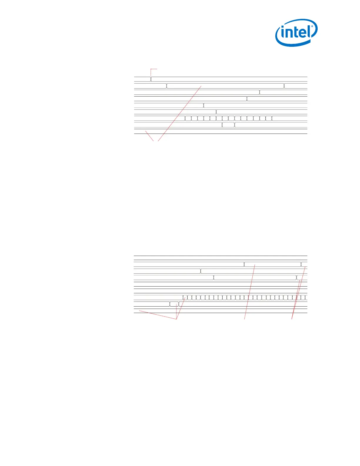
Figure 34. TX FIFO Pre-fill (6-lane Interface)
tx_enh_data_valid
tx_digitalreset
tx_enh_fifo_full
tx_enh_fifo_pfull
tx_enh_fifo_empty
tx_enh_fifo_pempty
tx_enh_fifo_cnt
tx_enh_frame
tx_enh_frame_burst_en
3f 00
00
00
00
3f
3f
000000
00
00
3f
3f
3f
00
00
003f
1... 2... 3... 4... 5... 6... 7... 8... 9... a... b... c... d... e... ffffff
Deassert tx_digitalreset
Deassert burst_en for all Lanes and Fill
TX FIFO Until all Lane FIFOs Are Full
After the TX FIFO pre-fill stage completes, the transmit lanes synchronize and the MAC
layer begins to send valid data to the transceiver’s TX FIFO. You must never allow the
TX FIFO to overflow or underflow. If it does, you must reset the transceiver and repeat
the TX FIFO pre-fill stage.
For a single lane Interlaken implementation, TX FIFO soft bonding is not required. You
can begin sending an Interlaken word to the TX FIFO after tx_digitalreset
deasserts.
The following figure shows the MAC layer sending valid data to the Native PHY after
the pre-fill stage. tx_enh_frame_burst_en is asserted, allowing the frame
generator to read data from the TX FIFO. The TX MAC layer can now control
tx_enh_data_valid and write data to the TX FIFO based on the FIFO status signals.
Figure 35. MAC Sending Valid Data (6-lane Interface)
tx_enh_data_valid
tx_digitalreset
tx_enh_fifo_full
tx_enh_fifo_pfull
tx_enh_fifo_empty
tx_enh_fifo_pempty
tx_enh_fifo_cnt
tx_enh_frame
tx_enh_frame_burst_en
3f
00
00
00
00
3f 00
00
3f
3f
3f
00
00
00
3f
ffffff
After the Pre-fill Stage, Assert burst_en.
The Frame Generator Reads Data from
the TX FIFO for the Next Metaframe
The User Logic Asserts data_valid
to Send Data to the TX FIFO Based
on the FIFO Status
The TX FIFO
Writes Backpressure
2.5.2.2.2. RX Multi-lane FIFO Deskew State Machine
Add deskew logic at the receiver side to eliminate the lane-to-lane skew created at the
transmitter of the link partner, PCB, medium, and local receiver PMA.
Implement a multi-lane alignment deskew state machine to control the RX FIFO
operation based on available RX FIFO status flags and control signals.
2. Implementing Protocols in Arria 10 Transceivers
UG-01143 | 2018.06.15
Intel
®
Arria
®
10 Transceiver PHY User Guide
101