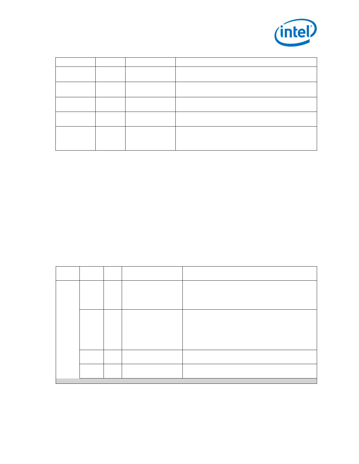
Signal Name Direction Clock Domain Description
mgmt_writeda
ta[31:0]
Input Synchronous to
mgmt_clk
Input data.
mgmt_readdat
a[31:0]
Output Synchronous to
mgmt_clk
Output data.
mgmt_write
Input Synchronous to
mgmt_clk
Write signal. Active high.
mgmt_read
Input Synchronous to
mgmt_clk
Read signal. Active high.
mgmt_waitreq
uest
Output Synchronous to
mgmt_clk
When asserted, indicates that the Avalon-MM slave interface is
unable to respond to a read or write request. When asserted,
control signals to the Avalon-MM slave interface must remain
constant.
Related Information
Avalon Interface Specifications
2.6.3.6.1. 10GBASE-KR PHY Register Definitions
The Avalon-MM slave interface signals provide access to the control and status
registers.
The following table specifies the control and status registers that you can access over
the Avalon-MM PHY management interface. A single address space provides access to
all registers.
Note: Unless otherwise indicated, the default value of all registers is 0.
Note: Writing to reserved or undefined register addresses may have undefined side effects.
Table 122. 10GBASE-KR Register Definitions
Word
Addr
Bit R/W Name Description
0x4B0 0 RW
Reset SEQ
When set to 1, resets the 10GBASE-KR sequencer (auto rate
detect logic), initiates a PCS reconfiguration, and may restart
Auto-Negotiation, Link Training or both if AN and LT are
enabled (10GBASE-KR mode). SEQ Force Mode[2:0] forces
these modes. This reset self clears.
1 RW
Disable AN Timer Auto-Negotiation disable timer. If disabled ( Disable AN
Timer = 1) , AN may get stuck and require software support
to remove the ABILITY_DETECT capability if the link partner
does not include this feature. In addition, software may have
to take the link out of loopback mode if the link is stuck in the
ACKNOWLEDGE_DETECT state. To enable this timer set
Disable AN Timer = 0.
2 RW
Disable LF Timer
When set to 1, disables the Link Fail timer. When set to 0, the
Link Fault timer is enabled.
3 RW
fail_lt_if_ber
When set to 1, the last LT measurement is a non-zero
number. Treat this as a failed run. 0 = normal.
continued...
2. Implementing Protocols in Arria 10 Transceivers
UG-01143 | 2018.06.15
Intel
®
Arria
®
10 Transceiver PHY User Guide
149