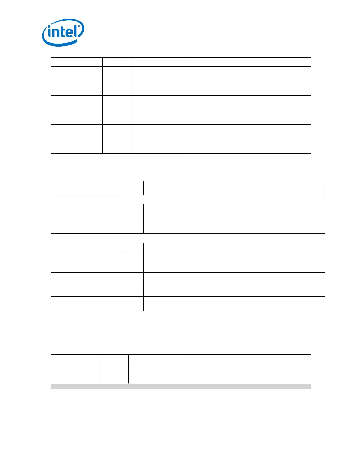
Signal Name Direction Clock Domain Description
tx_latency_adj_10
g[15:0]
Output Synchronous to
xgmii_tx_clk
When you enable 1588, this signal outputs the real time
latency in XGMII clock cycles (156.25 MHz) for the TX
PCS and PMA datapath for 10G mode. Bits 0 to 9
represent the fractional number of clock cycles. Bits 10 to
15 represent the number of clock cycles.
rx_latency_adj_1
g[21:0]
Output Synchronous to
gmii_rx_clk
When you enable 1588, this signal outputs the real time
latency in GMII clock cycles (125 MHz) for the RX PCS and
PMA datapath for 1G mode. Bits 0 to 9 represent the
fractional number of clock cycles. Bits 10 to 21 represent
the number of clock cycles.
tx_latency_adj_1
g[21:0]
Output Synchronous to
gmii_tx_clk
When you enable 1588, this signal outputs the real time
latency in GMII clock cycles (125 MHz) for the TX PCS and
PMA datapath for 1G mode. Bits 0 to 9 represent the
fractional number of clock cycles. Bits 10 to 21 represent
the number of clock cycles.
2.6.4.6.7. MII
Table 142. MII Signals
Name Directi
on
Description
MII Transmit Interface
mii_tx_d[3:0]
Input MII transmit data bus.
mii_tx_en
Input
Assert this signal to indicate that the data on mii_tx_d[3:0]is valid.
mii_tx_err
Input Assert this signal to indicate to the PHY device that the frame sent is invalid.
MII Receive Interface
mii_rx_d[3:0]
Output MII receive data bus.
mii_rx_dv
Output
Asserted to indicate that the data on mii_rx_d[3:0]is valid. The signal stays
asserted during frame reception, from the first preamble byte until the last byte of
the CRC field is received.
mii_rx_err
Output Asserted by the PHY to indicate that the current frame contains errors.
mii_col
Output Collision detection. Asserted by the PCS function to indicate that a collision was
detected during frame transmission.
mii_crs
Output Carrier sense detection. Asserted by the PCS function to indicate that a transmit or
receive activity is detected on the Ethernet line.
2.6.4.6.8. Dynamic Reconfiguration Interface
You can use the dynamic reconfiguration interface signals to dynamically change
between 1G and 10G data rates.
Table 143. Dynamic Reconfiguration Interface Signals
Signal Name Direction Clock Domain Description
rc_busy
Output Synchronous to
mgmt_clk
When asserted, indicates that reconfiguration is in
progress. Synchronous to the mgmt_clk. This signal is
only exposed under the following condition:
continued...
2. Implementing Protocols in Arria 10 Transceivers
UG-01143 | 2018.06.15
Intel
®
Arria
®
10 Transceiver PHY User Guide
180
 Loading...


