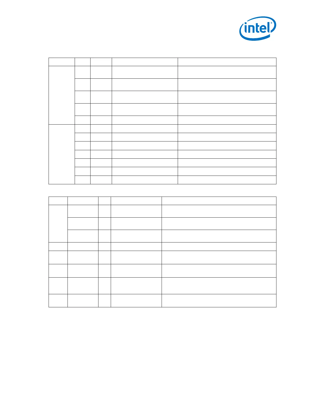
Table 148. 1G Data Mode
Addr Bit R/W Name Description
0x4A8 0 RW
tx_invpolarity
When set, the TX interface inverts the polarity of
the TX data to the 8B/10B encoder.
1 RW
rx_invpolarity
When set, the RX channels inverts the polarity of
the received data to the 8B/10B decoder.
2 RW
rx_bitreversal_enable
When set, enables bit reversal on the RX interface
to the word aligner.
3 RW
rx_bytereversal_enable
When set, enables byte reversal on the RX interface
to the byte deserializer.
4 RW
force_electrical_idle
When set, forces the TX outputs to electrical idle.
0x4A9 0 R
rx_syncstatus
When set, the word aligner is synchronized.
1 R
rx_patterndetect
GbE word aligner detected comma.
2 R
rx_rlv
Run length violation.
3 R
rx_rmfifodatainserted
Rate match FIFO inserted code group.
4 R
rx_rmfifodatadeleted
Rate match FIFO deleted code group.
5 R
rx_disperr
RX 8B10B disparity error.
6 R
rx_errdetect
RX 8B10B error detected.
Table 149. PMA Registers
Address Bit R/W Name Description
0x444 1 RW
reset_tx_digital
Writing a 1 asserts the internal TX digital reset signal. You
must write a 0 to clear the reset condition.
2 RW
reset_rx_analog
Writing a 1 causes the internal RX analog reset signal to be
asserted. You must write a 0 to clear the reset condition.
3 RW
reset_rx_digital
Writing a 1 causes the internal RX digital reset signal to be
asserted. You must write a 0 to clear the reset condition.
0x461 0 RW
phy_serial_loopback
Writing a 1 puts the channel in serial loopback mode.
0x464 0 RW
pma_rx_set_locktoda
ta
When set, programs the RX clock data recovery (CDR) PLL
to lock to the incoming data.
0x465 0 RW
pma_rx_set_locktore
f
When set, programs the RX CDR PLL to lock to the reference
clock.
0x466 0 RO
pma_rx_is_lockedtod
ata
When asserted, indicates that the RX CDR PLL is locked to
the RX data, and that the RX CDR has changed from LTR to
LTD mode.
0x467 0 RO
pma_rx_is_lockedtor
ef
When asserted, indicates that the RX CDR PLL is locked to
the reference clock.
2. Implementing Protocols in Arria 10 Transceivers
UG-01143 | 2018.06.15
Intel
®
Arria
®
10 Transceiver PHY User Guide
195