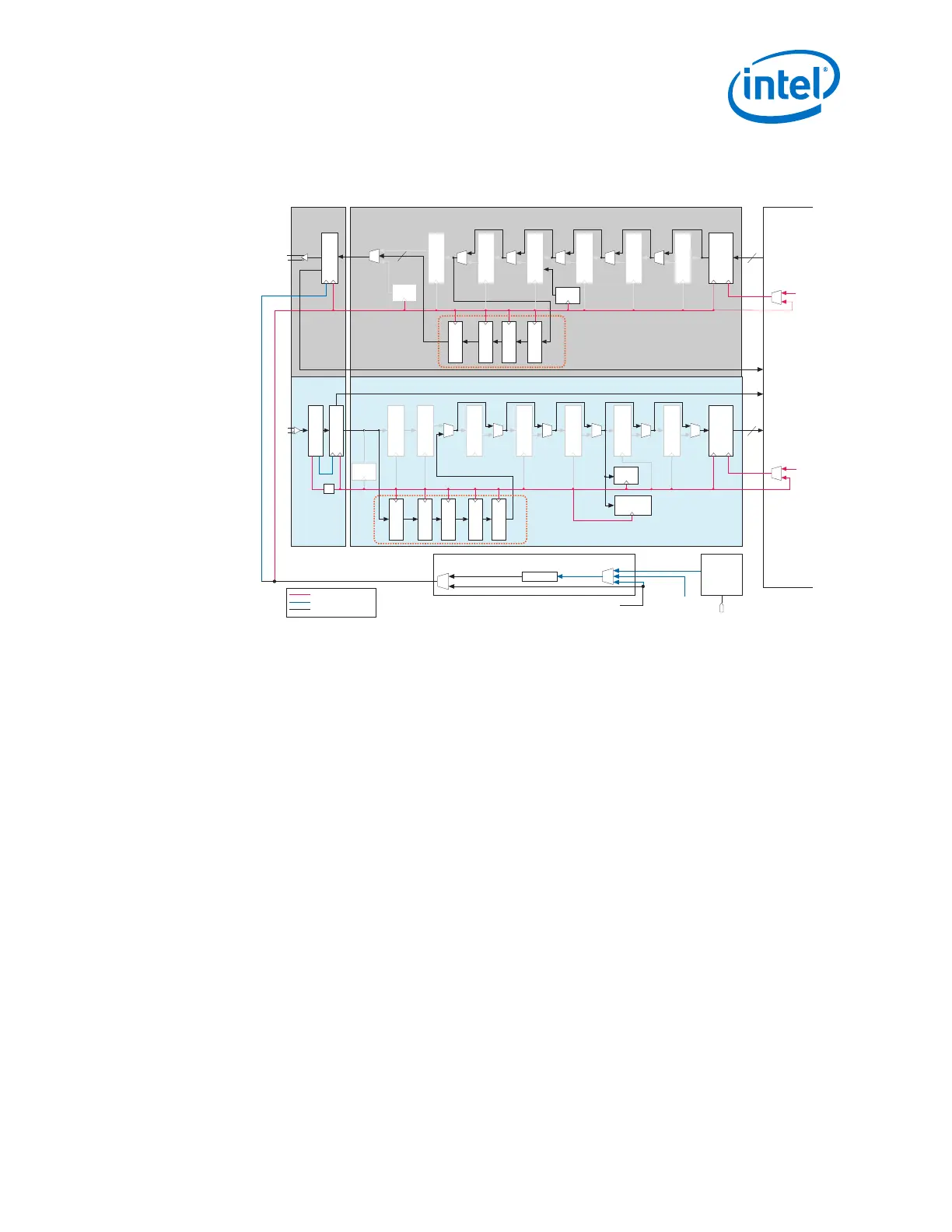
Figure 122. Transceiver Channel Datapath and Clocking for a Basic with KR FEC
Configuration
Clock frequencies in this figure are examples based on a 10.3125 Gbps data rate.
Transmitter Enhanced PCSTransmitter PMA
Receiver PMA
Receiver Enhanced PCS
TX
Gearbox
tx_serial_data
Serializer
Interlaken
Disparity Generator
Scrambler
KR FEC
KR FEC
tx_pma_clk
tx_krfec_clk
PRBS
Generator
PRP
Generator
rx_serial_data
Deserializer
CDR
Descrambler
Interlaken
Disparity Checker
Block
Synchronizer
Interlaken
Frame Sync
RX
Gearbox
PRBS
Verifier
Transcode
Decoder
KR FEC RX
Gearbox
KR FEC
Decoder
KR FEC
Block Sync
KR FEC
Descrambler
rx_pma_clk
rx_krfec_clk
Parallel Clock
Serial Clock
Parallel and Serial Clocks
Clock Divider
/64
Parallel and Serial Clocks
Clock Generation Block (CGB)
Serial Clock
rx_rcvd_clk
tx_hf_clk
tx_serial_clk0
(5156.25 MHz) =
Data rate/2
Input Reference Clock
ATX PLL
fPLL
CMU PLL
64B/66B Decoder
and RX SM
10GBASE-R
BER Checker
PRP
rx_pma_div_clkout
tx_pma_div_clkout
Verifier
rx_coreclkin
rx_clkout
Enhanced PCS
TX FIFO
Enhanced PCS
RX FIFO
Interlaken
Frame Generator
Interlaken
CRC32 Generator
Interlaken
CRC32 Checker
64B/66B Encoder
and TX SM
FPGA
Fabric
tx_coreclkin
tx_clkout
KR FEC
TX Gearbox
KR FEC
Scrambler
KR FEC
Encoder
Transcode
Encoder
64
Notes:
1. Value is based on the clock division factor chosen
2. Value is calculated as data rate on parallel interface/FPGA fabric - PCS interface width
3. Value is calculated as data rate on serial interface/PCS-PMA interface width
5156.25 MHz (10.3125 Gbps data rate/2) (1)
TX
Data &
Control
64 + 2
RX
Data &
Control
64 + 2
Parallel Clock (161.13 MHz) (3)
Parallel Clock (161.13 MHz) (3)
@ 156.25 MHz
@ 156.25 MHz
156.25 MHz (2)
156.25 MHz (2)
2.9.1.1. How to Implement the Basic (Enhanced PCS) and Basic with KR FEC
Transceiver Configuration Rules in Arria 10 Transceivers
You should be familiar with the Basic (Enhanced PCS) and PMA architecture, PLL
architecture, and the reset controller before implementing the Basic (Enhanced PCS)
or Basic with KR FEC Transceiver Configuration Rule.
1. Open the IP Catalog and select the Arria 10 Transceiver Native PHY IP.
Refer to Select and Instantiate the PHY IP Core on page 33 for more details.
2. Select Basic (Enhanced PCS) or Basic with KR FEC from the Transceiver
Configuration Rules list located under Datapath Options.
3. Use the parameter values in the tables in Transceiver Native PHY IP Parameters for
Basic (Enhanced PCS) and Basic with KR FEC Transceiver Configuration Rules as a
starting point. Or, you can use the protocol presets described in Transceiver Native
PHY Presets. You can then modify the settings to meet your specific requirements.
4. Click Finish to generate the Native PHY IP (this is your RTL file).
2. Implementing Protocols in Arria 10 Transceivers
UG-01143 | 2018.06.15
Intel
®
Arria
®
10 Transceiver PHY User Guide
291