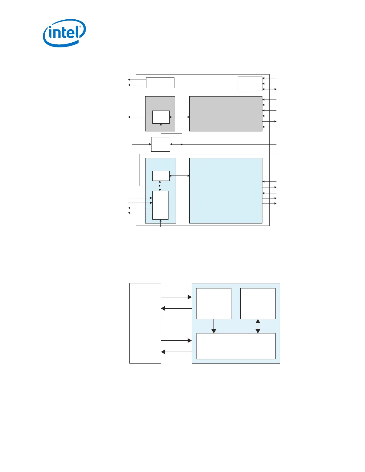
Figure 123. Signals and Ports of Native PHY IP for Basic (Enhanced PCS) and Basic with
KR FEC Configurations
Reconfiguration
Registers
NIOS
Hard Calibration IP
TX PMA
Serializer
tx_serial_data
tx_serial_clk0
(from TX PLL)
rx_cal_busy
tx_cal_busy
rx_serial_data
rx_control[19:0]
rx_cdr_refclk0
rx_is_lockedtodata
rx_is_lockedtoref
rx_parallel_data[127:0]
tx_control[17:0] tx_control[17:0]
tx_digital_resettx_digital_reset
tx_parallel_data[127:0]
reconfig_clk
reconfig_avmm
reconfig_reset
tx_coreclkin
tx_clkout
tx_enh_data_valid
tx_parallel_data[127:0]
tx_coreclkin
tx_clkout
tx_enh_data_valid
RX PMA
TX Enhanced PCS
RX Enhanced PCS
Deserializer
Clock
Generation
Block
rx_cdr_refclk0
CDR
rx_clkout
rx_coreclkin
rx_clkout
rx_coreclkin
rx_analog_reset
tx_analog_reset
rx_digital_resetrx_digital_reset
rx_parallel_data[127:0]
rx_control[19:0]
5. Configure and instantiate the PLL.
6. Create a transceiver reset controller. You can use your own reset controller or use
the Transceiver PHY Reset Controller.
7. Connect the Native PHY IP core to the PLL IP core and the reset controller.
Figure 124. Connection Guidelines for a Basic (Enhanced PCS) Transceiver Design
Reset
Controller
Arria 10 Transceiver
Native PHY
Design
Testbench
32-bit data
(32:32
gearbox ratio)
PLL IP Core
2. Implementing Protocols in Arria 10 Transceivers
UG-01143 | 2018.06.15
Intel
®
Arria
®
10 Transceiver PHY User Guide
292