Note: •
rx_patterndetect is asserted whenever there is a pattern match.
•
rx_syncstatus is asserted after the word aligner achieves synchronization.
•
rx_std_wa_patternalign is asserted to re-align and resynchronize.
•
If there is more than one channel in the design, rx_patterndetect,
rx_syncstatus and rx_std_wa_patternalign become buses in which each
bit corresponds to one channel.
You can verify this feature by monitoring rx_parallel_data.
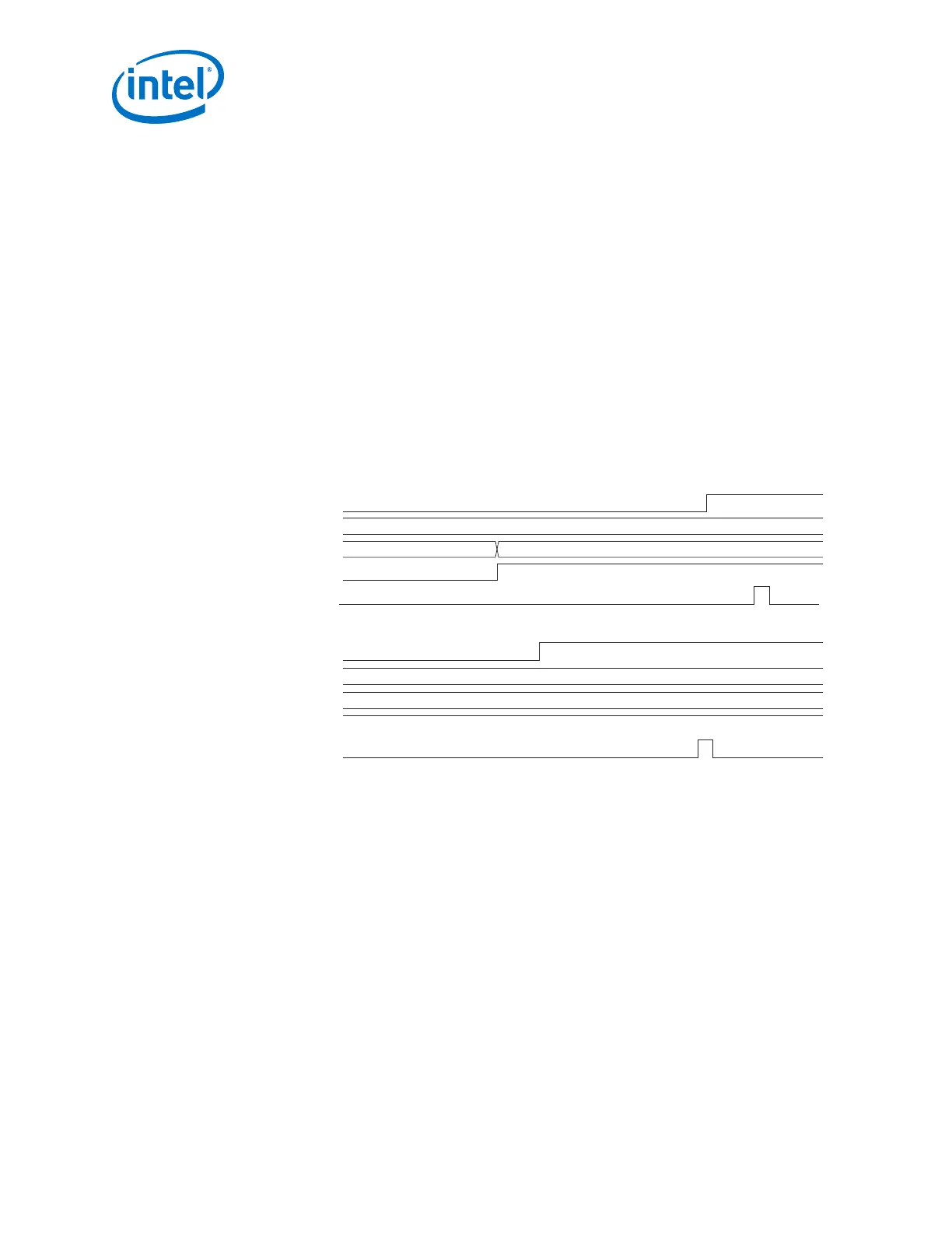
The following timing diagrams demonstrate how to use the ports and show the
relationship between the various control and status signals. In the top waveform,
rx_parallel_data is initially misaligned. After asserting the
rx_std_wa_patternalign signal, it becomes aligned. The bottom waveform shows
the behavior of the rx_syncstatus signal when rx_parallel_data is already
aligned.
Figure 132. Manual Mode when the PCS-PMA Interface Width is 8 Bits
tx_parallel_data = 8'hBC and the word aligner pattern = 8'hBC
rx_std_wa_patternalign
tx_parallel_data
rx_parallel_data
rx_patterndetect
rx_syncstatus
rx_std_wa_patternalign
tx_parallel_data
rx_parallel_data
rx_patterndetect
rx_syncstatus
bc
00 bc
bc
bc
In manual alignment mode, the word alignment operation is manually controlled with
the rx_std_wa_patternalign input signal or the rx_enapatternalign register.
The word aligner operation is level-sensitive to rx_enapatternalign. The word
aligner asserts the rx_syncstatus signal for one parallel clock cycle whenever it re-
aligns to the new word boundary.
2. Implementing Protocols in Arria 10 Transceivers
UG-01143 | 2018.06.15
Intel
®
Arria
®
10 Transceiver PHY User Guide
302