The 8B/10B encoder and decoder add the following additional ports:
•
tx_datak
•
rx_datak
•
rx_errdetect
•
rx_disperr
•
rx_runningdisp
1. Set the RX word aligner mode to synchronous state machine.
2. Set the RX word aligner pattern length option according to the PCS-PMA
interface width.
3. Enter a hexadecimal value in the RX word aligner pattern (hex) field.
The RX word aligner pattern is the 8B/10B encoded version of the data pattern. You
can also specify the number of word alignment patterns to achieve synchronization,
the number of invalid data words to lose synchronization, and the number of valid
data words to decrement error count. This mode adds two additional ports:
rx_patterndetect and rx_syncstatus.
Note: •
rx_patterndetect is asserted whenever there is a pattern match.
•
rx_syncstatus is asserted after the word aligner achieves synchronization.
•
rx_std_wa_patternalign is asserted to re-align and re-synchronize.
•
If there is more than one channel in the design, tx_datak, rx_datak,
rx_errdetect, rx_disperr, rx_runningdisp, rx_patterndetect, and
rx_syncstatus become buses in which each bit corresponds to one channel.
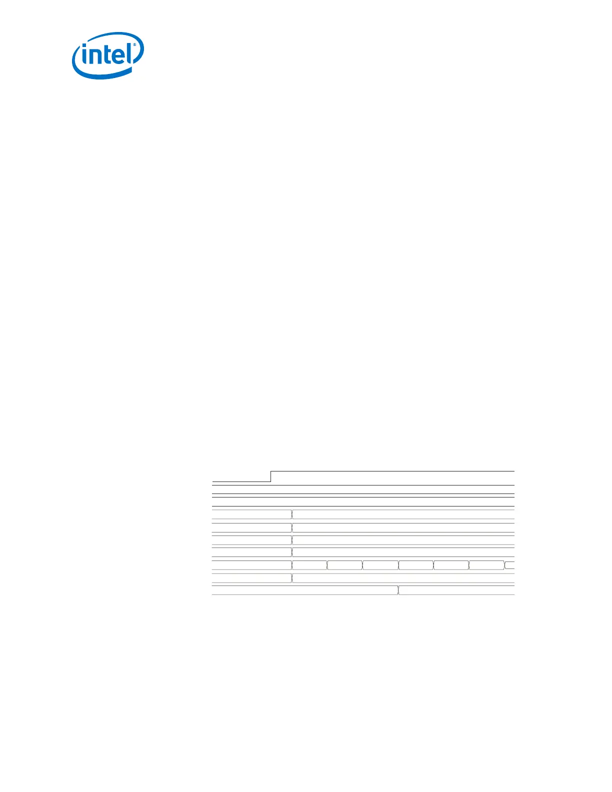
You can verify this feature by monitoring rx_parallel_data.
Figure 136. Synchronization State Machine Mode when the PCS-PMA Interface Width is
20 Bits
tx_datak
tx_parallel_data
rx_parallel_data
rx_datak
rx_errdetect
rx_disperr
rx_runningdisp
rx_patterndetect
rx_syncstatus
11
bc02
0000
00
11
11
00
00
00
02bc
01
11
00
00
00
01
11 00 11 00 11
11
rx_std_wa_patternalign
2.9.2.3. RX Bit Slip
To use the RX bit slip, select Enable rx_bitslip port and set the word aligner mode to
bit slip. This adds rx_bitslip as an input control port. An active high edge on
rx_bitslip slips one bit at a time. When rx_bitslip is toggled, the word aligner
slips one bit at a time on every active high edge. Assert the rx_bitslip signal for at
least two parallel clock cycles to allow synchronization. You can verify this feature by
monitoring rx_parallel_data.
2. Implementing Protocols in Arria 10 Transceivers
UG-01143 | 2018.06.15
Intel
®
Arria
®
10 Transceiver PHY User Guide
304