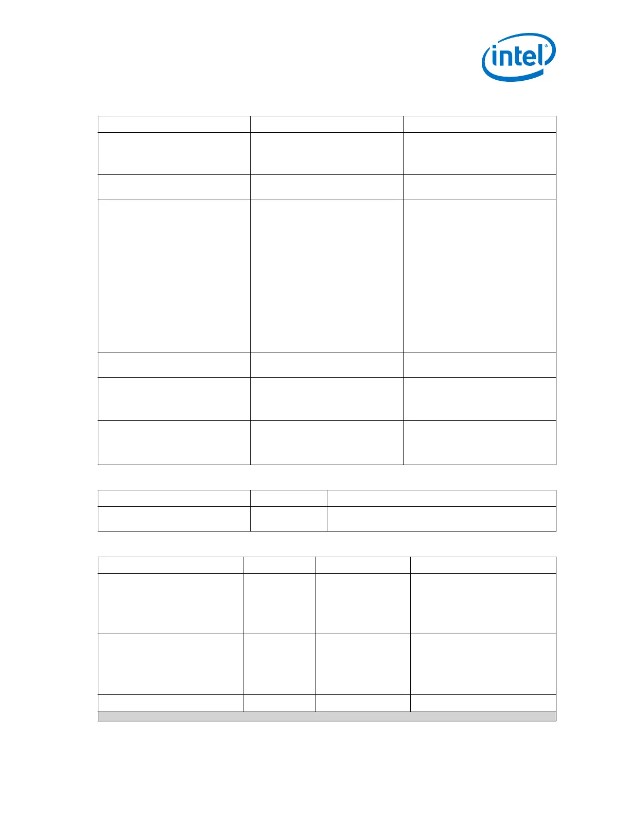
Table 237. Clock Switchover (between Dynamic Reconfiguration and General Options)
Clock Switchover Parameter Range Description
Create a second input clock
pllrefclk1
On/Off Turn on this parameter to have a
backup clock attached to your fPLL that
can switch with your original reference
clock
Second Reference Clock Frequency User Defined Specifies the second reference clock
frequency for fPLL
Switchover Mode Automatic Switchover
Manual Switchover
Automatic Switchover with Manual
Override
Specifies how Input frequency
switchover is handled. Automatic
Switchover uses built in circuitry to
detect if one of your input clocks has
stopped toggling and switch to the
other.
Manual Switchover creates an
EXTSWITCH signal which can be used
to manually switch the clock by
asserting high for at least 3 cycles.
Automatic Switchover with Manual
Override acts as Automatic Switchover
until the EXTSWITCH goes high, in
which case it switches and ignores any
automatic switches as long as
EXTSWITCH stays high.
Switchover Delays 0 to 7 Adds a specific amount of cycle delay
to the Switchover Process.
Create an active_clk signal to
indicate the input clock in use
On/Off This parameter creates an output that
indicates which input clock is currently
in use by the PLL. Low indicates
refclk, High indicates refclk1.
Create a clkbad signal for each of
the input clocks
On/Off
This parameter creates two clkbad
outputs, one for each input clock. Low
indicates the CLK is working, High
indicates the CLK is not working.
Table 238. fPLL - Generation Options
Parameter Direction Description
Generates parameter
documentation file
On/Off Generates a .csv file that contains descriptions of all the
fPLL parameters and values.
Table 239. fPLL IP Core Ports
Port Direction Clock Domain Description
pll_powerdown input Asynchronous Resets the PLL when asserted high.
Needs to be connected to a
dynamically controlled signal (the
Transceiver PHY Reset Controller
pll_powerdown output if using this
Intel FPGA IP).
pll_refclk0 input N/A Reference clock input port 0.
There are five reference clock input
ports. The number of reference clock
ports available depends on the
Number of PLL reference clocks
parameter.
pll_refclk1
input N/A Reference clock input port 1.
continued...
3. PLLs and Clock Networks
UG-01143 | 2018.06.15
Intel
®
Arria
®
10 Transceiver PHY User Guide
365