• Set the Native PHY IP core TX Channel bonding mode to Non-Bonded.
• Set the number of channels as per your design requirement. In this example,
the number of channels is set to 10.
4. Create a top level wrapper to connect the PLL IP core to the Native PHY IP core.
•
The tx_serial_clk output port of the PLL IP core represents the high
speed serial clock.
•
The Native PHY IP core has 10 (for this example) tx_serial_clk input
ports. Each port corresponds to the input of the local CGB of the transceiver
channel.
•
As shown in the figure above, connect the first 6 tx_serial_clk input to
the first transceiver PLL instance.
•
Connect the remaining 4 tx_serial_clk input to the second transceiver
PLL instance.
3.11.1.3. Implementing Multi-Channel xN Non-Bonded Configuration
Using the xN non-bonded configuration reduces the number of PLL resources and the
reference clock sources used.
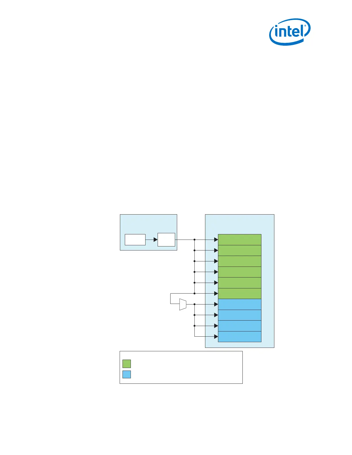
Figure 192. PHY IP Core and PLL IP Core Connection for Multi-Channel xN Non-Bonded
Configuration
In this example, the same PLL is used to drive 10 channels across two transceiver banks.
Transceiver PLL
Instance (5 GHz)
ATX PLL
Native PHY Instance
(10 CH Non-Bonded 10 Gbps)
TX Channel
TX Channel
TX Channel
TX Channel
TX Channel
TX Channel
TX Channel
TX Channel
TX Channel
TX Channel
Master
CGB
xN
Legend:
TX channels placed in the adjacent transceiver bank.
TX channels placed in the same transceiver bank.
x1
x6
3. PLLs and Clock Networks
UG-01143 | 2018.06.15
Intel
®
Arria
®
10 Transceiver PHY User Guide
401