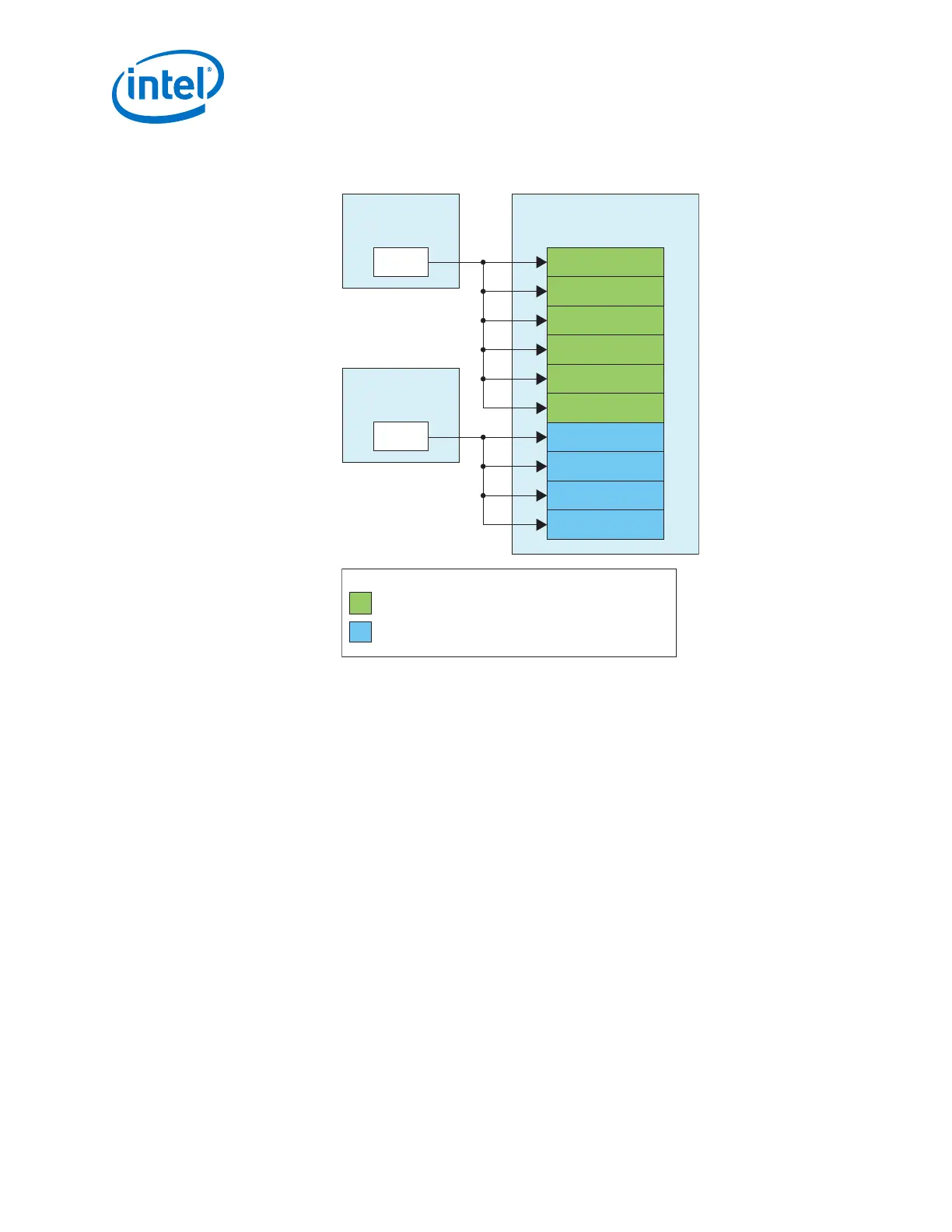
Figure 191. PHY IP Core and PLL IP Core Connection for Multi-Channel x1 Non-Bonded
Configuration
Transceiver PLL
Instance (5 GHz)
fPLL
Transceiver PLL
Instance (5 GHz)
fPLL
Native PHY Instance
(10 CH Non-Bonded 10 Gbps)
TX Channel
TX Channel
TX Channel
TX Channel
TX Channel
TX Channel
TX Channel
TX Channel
TX Channel
TX Channel
Legend:
TX channels placed in the adjacent transceiver bank.
TX channels placed in the same transceiver bank.
Steps to implement a Multi-Channel x1 Non-Bonded Configuration
1. Choose the PLL IP core (ATX PLL, fPLL, or CMU PLL) you want to instantiate in
your design and instantiate the PLL IP core.
• Refer to Instantiating the ATX PLL IP Core on page 354 or Instantiating CMU
PLL IP Core on page 370 or Instantiating the fPLL IP Core on page 362 for
detailed steps.
2. Configure the PLL IP core using the IP Parameter Editor
• For the ATX PLL IP core do not include the Master CGB. If your design uses the
ATX PLL IP core and more than 6 channels, the x1 Non-Bonded Configuration
is not a suitable option. Multi-channel xN Non-Bonded or Multi-Channel x1/xN
Non-Bonded are the required configurations when using the ATX PLL IP core
and more than 6 channels in the Native PHY IP core.
• Refer to Figure 192 on page 401 Implementing Multi-Channel xN Non-Bonded
Configuration section or the Figure 193 on page 403 Multi-Channel x1/xN Non-
Bonded Example.
• For the fPLL IP core, set the PLL feedback operation mode to direct.
• For the CMU PLL IP core, specify the reference clock and the data rate. No
special configuration rule is required.
3. Configure the Native PHY IP core using the IP Parameter Editor
3. PLLs and Clock Networks
UG-01143 | 2018.06.15
Intel
®
Arria
®
10 Transceiver PHY User Guide
400