and DC gain values cannot be controlled individually as done in high gain mode. The
recommended AC gain values in high data rate mode include the appropriate setting
of DC gain to get the required peaking at respective peaking frequencies.
CTLE can only be supported in manual mode with the exception of PCIe Gen3, which
supports triggered mode. CTLE mode and CTLE gain can be set through Quartus
Assignment Editor or Quartus Settings File and Avalon MM registers.
Related Information
• CTLE Settings in Triggered Adaptation Mode on page 531
• PHY IP Core for PCIe (PIPE) Link Equalization for Gen3 Data Rate on page 274
• How to Enable CTLE and DFE on page 456
• Arria 10 Device Datasheet
• Arria 10 Register Map
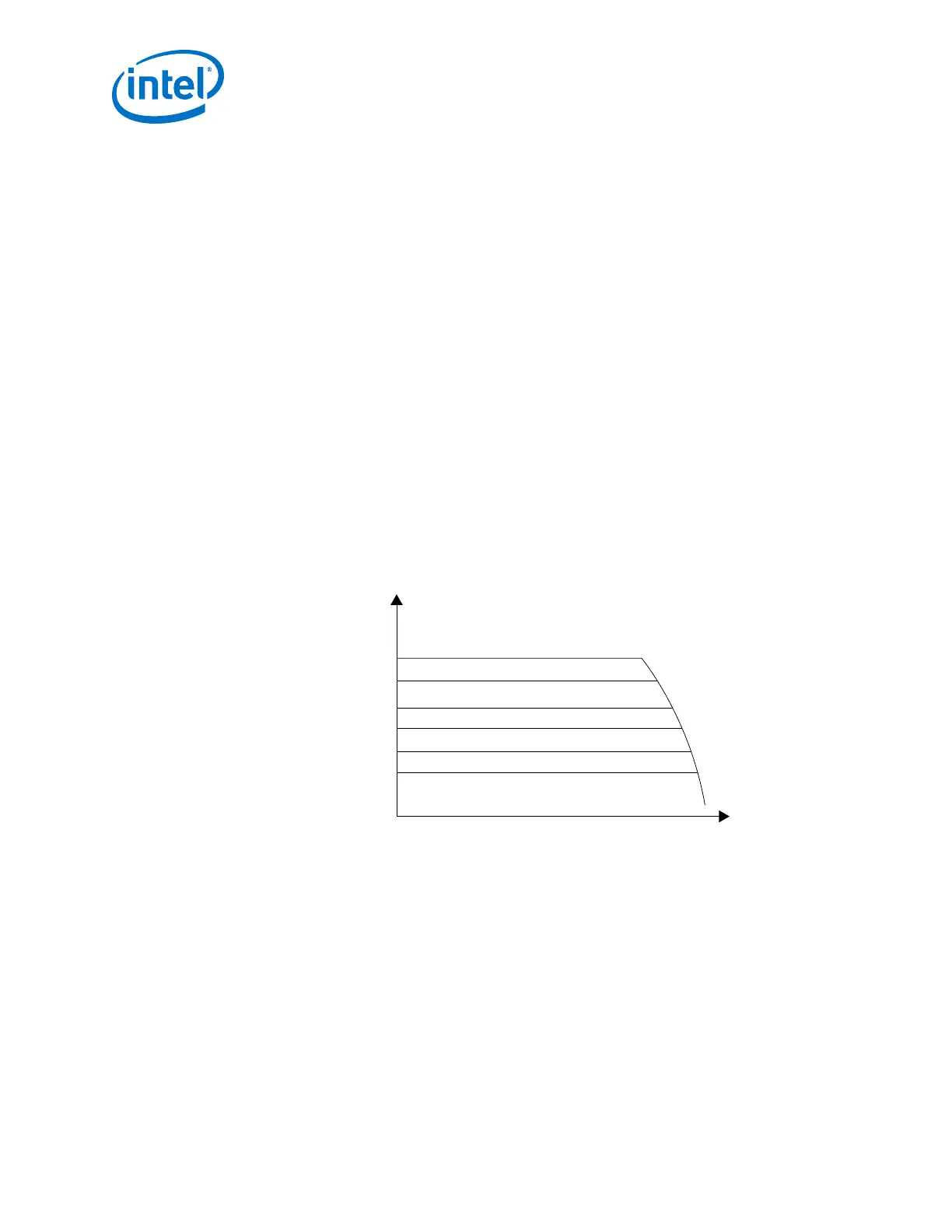
5.1.2.1.5. Variable Gain Amplifier (VGA)
Arria 10 channels have a variable gain amplifier to optimize the signal amplitude prior
to the CDR sampling. VGA can only be operated in manual mode. VGA gain can be
selected through Quartus Assignment Editor or Quartus Setting File (qsf) or the
Avalon MM register. You must set VGA manually for all combinations of CTLE and DFE
modes.
Figure 228. VGA Frequency Response for Different Gain Settings
6
-4
Magnitude
(dB)
Frequency (Hz)
Related Information
How to Enable CTLE and DFE on page 456
5.1.2.1.6. Decision Feedback Equalization (DFE)
DFE amplifies the high frequency components of a signal without amplifying the noise
content. It compensates for inter-symbol interference (ISI). DFE minimizes post-
cursor ISI by adding or subtracting weighted versions of the previously received bits
from the current bit. DFE works in synchronization with the TX pre-emphasis and
downstream RX CTLE. This enables the RX CDR to receive the correct data that was
transmitted through a lossy and noisy backplane.
5. Arria 10 Transceiver PHY Architecture
UG-01143 | 2018.06.15
Intel
®
Arria
®
10 Transceiver PHY User Guide
454