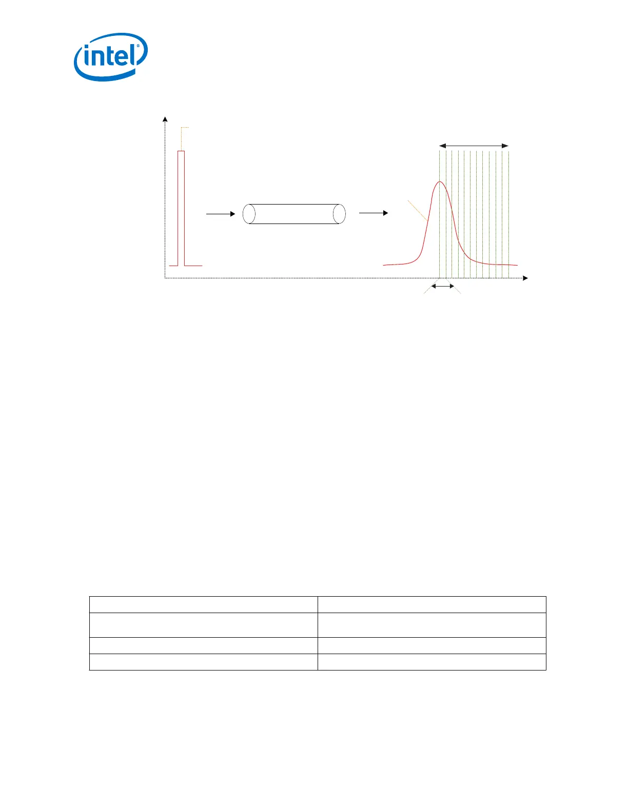
Figure 230. Channel Pulse Response
V
t
1UI
Region of Influence
for Fixed Taps
Signal at the
Channel Input
Signal at the
Channel Output
Transmission Medium
Note: The pulse at the output of the channel shows a long decaying tail. Frequency-
dependent losses and quality degradation affects other signals.
Supported modes for DFE:
• Disabled Mode:
— DFE disabled mode is similar to DFE manual mode, except all DFE tap values
in this mode are set to zero. DFE tap values can be set in Assignment
Editor/.qsf or using Avalon MM interface.
• Manual Mode:
— In this mode, manual DFE tap values can be set in Assignment Editor/.qsf or
using Avalon MM interface.
• Adaptation Enabled Mode:
— In this adaptation mode, DFE tap values are controlled by the Adaptive
Parametric Tuning Engine. This mode uses the converged DFE tap values given
by the Adaptive Parametric Tuning Engine.
Related Information
How to Enable CTLE and DFE on page 456
5.1.2.1.7. How to Enable CTLE and DFE
Table 252. Summary of Receiver Equalization Modes
Receiver Equalization Modes
CTLE adaptation mode Manual, Triggered (use the triggered mode for PCIe Gen3
only)
DFE adaptation mode Adaptation enabled, Manual, Disabled
Number of fixed DFE taps 3, 7, 11
Follow these steps to trigger DFE adaptation:
5. Arria 10 Transceiver PHY Architecture
UG-01143 | 2018.06.15
Intel
®
Arria
®
10 Transceiver PHY User Guide
456