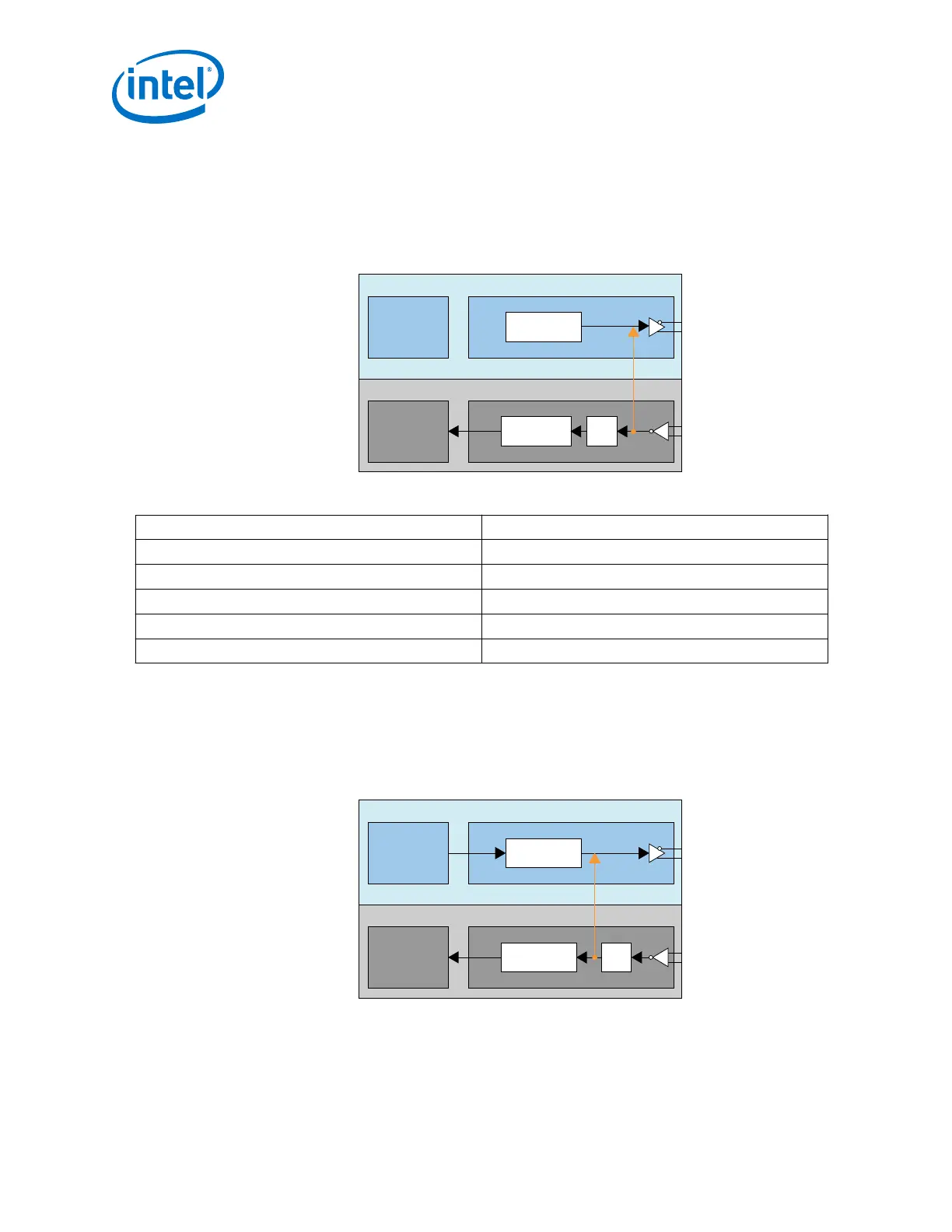
Reverse Serial Loopback Mode (Pre-CDR)
In the pre-CDR mode, data received through the RX input buffer is looped back to the
TX output buffer. You can enable the reverse serial loopback mode by performing
read-modify-write to the following registers.
Figure 274. Reverse Serial Loopback Mode (Pre-CDR)
PCS PMA
Serializer
PCS PMA
Deserializer
Transmitter
Receiver
CDR
Pre-CDR Reverse
Serial Loopback
Table 277. Bit Values to Be Set
Address Bit Values
0x137[7] 1’b1
0x13C[7] 1’b0
0x132[5:4] 2’b00
0x142[4] 1’b1
0x11D[0] 1’b1
Reverse Serial Loopback Mode (Post-CDR)
In the post-CDR mode, received data passes through the RX CDR and then loops back
to the TX output buffer. Perform read-modify-write to the following registers to enable
this mode.
Figure 275. Reverse Serial Loopback Mode (Post-CDR)
PCS PMA
Serializer
PCS PMA
Transmitter
Receiver
Deserializer CDR
Post-CDR Reverse
Serial Loopback
6. Reconfiguration Interface and Dynamic Reconfiguration
UG-01143 | 2018.06.15
Intel
®
Arria
®
10 Transceiver PHY User Guide
534