Installing a 7360 ISAM FX-12 shelf
158
ANSI Hardware Installation Manual
3HH-12893-AAAA-TCZZA Issue: 09
DRAFT
Procedure 30 To install a 7360 ISAM FX-12 heat and fiber baffle kit
Use this procedure to install the upper baffle assembly of a heat and fiber baffle kit above a shelf,
and the lower baffle below a shelf. Also use this procedure for replacement in an existing 7360
ISAM FX-12 rack configuration.
1 Unpack and visually inspect the heat and fiber baffle kit for physical damage.
2 If anything is missing or damaged, notify the transportation carrier and Nokia immediately.
Photograph all the damaged equipment. Keep all the inspection and packing documents as
a reference.
3 Put on the antistatic wrist strap and connect it to a grounding point.
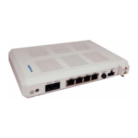
4 Verify the shelf unit and heat and fiber baffle kit mounting positions; see Figure 71.
5 Lift the pre-assembled upper baffle assembly of the heat and fiber baffle kit over the top of
the installed shelf and then push downward until the support bracket located inside the air
baffle connects with the top of the shelf.
Figure 72 shows the pre-assembled upper baffle assembly of the 7360 ISAM FX-12 heat and
fiber baffle kit.
Note — The 7360 ISAM FX-12 shelf must be installed prior to installing
the heat and fiber baffle kit.
Warning — Possibility of equipment damage.
Do not install damaged equipment, as it can adversely affect other
equipment.
 Loading...