Installing cards in the 7360 ISAM WM shelf
426
ANSI Hardware Installation Manual
3HH-12893-AAAA-TCZZA Issue: 09
DRAFT
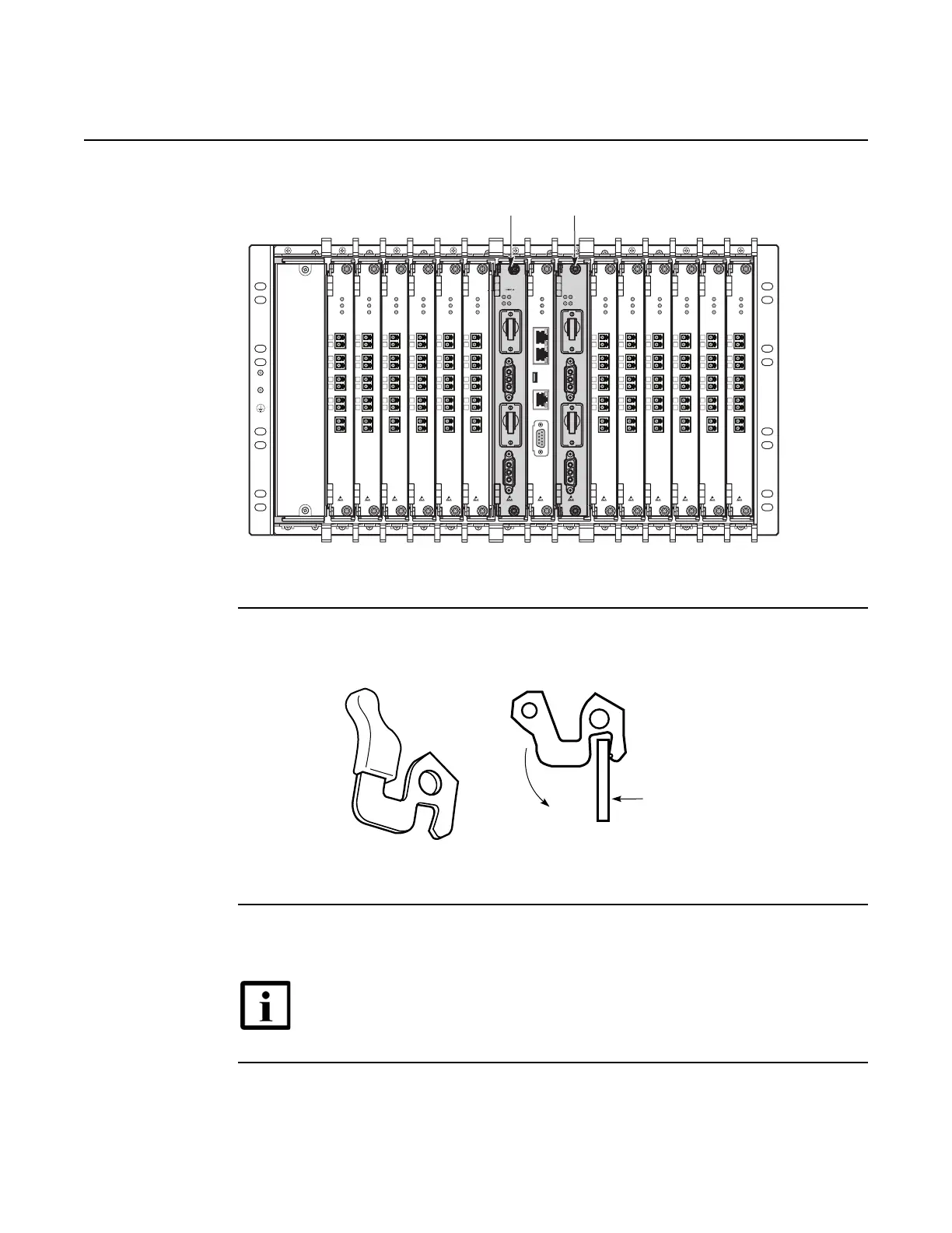
Figure 251 7360 ISAM WM power card slots
3 Use the ejector handles to engage the card connectors in the backplane, see Figure 252.
Figure 252 Ejector handles for 7360 ISAM WM cards
4 Lock the card in place with the fixation screws located at the top and bottom of the faceplate
of the card. The maximum torque is 0.3 Nm.
Note — Once the board is mounted in its slot, the green PWR LED lights
up.
25792
ALM
PW2
S1
PW1
PW2
S2
RUN
PW1
ALM
PW2
S1
PW1
PW2
S2
RUN
PW1
FWPC-A
USB
COM
ALARM
ALM
PWR
RUN
FWCC-A
GE1
GE2
1
2
3
4
1
2
3
4
A
B
PORT A
PORT B
ODN
ALM
PWR
PW1
FWLC-A
1
2
3
4
1
2
3
4
A
B
PORT A
PORT B
ODN
ALM
PWR
PW1
FWLC-A
1
2
3
4
1
2
3
4
A
B
PORT A
PORT B
ODN
ALM
PWR
PW1
FWLC-A
1
2
3
4
1
2
3
4
A
B
PORT A
PORT B
ODN
ALM
PWR
PW1
FWLC-A
1
2
3
4
1
2
3
4
A
B
PORT A
PORT B
ODN
ALM
PWR
PW1
FWLC-A
1
2
3
4
1
2
3
4
A
B
PORT A
PORT B
ODN
ALM
PWR
PW1
FWLC-A
1
2
3
4
1
2
3
4
A
B
PORT A
PORT B
ODN
ALM
PWR
PW1
FWLC-A
1
2
3
4
1
2
3
4
A
B
PORT A
PORT B
ODN
ALM
PWR
PW1
FWLC-A
1
2
3
4
1
2
3
4
A
B
PORT A
PORT B
ODN
ALM
PWR
PW1
FWLC-A
1
2
3
4
1
2
3
4
A
B
PORT A
PORT B
ODN
ALM
PWR
PW1
FWLC-A
1
2
3
4
1
2
3
4
A
B
PORT A
PORT B
ODN
ALM
PWR
PW1
FWLC-A
1
2
3
4
1
2
3
4
A
B
PORT A
PORT B
ODN
ALM
PWR
PW1
FWLC-A
1
2
FWP
-A
1
2
Withdrawl
Guiding plate
22376

 Loading...