ANSI Hardware Installation Manual 7360 ISAM FX-8 shelf cabling
Issue: 09 3HH-12893-AAAA-TCZZA 281
DRAFT
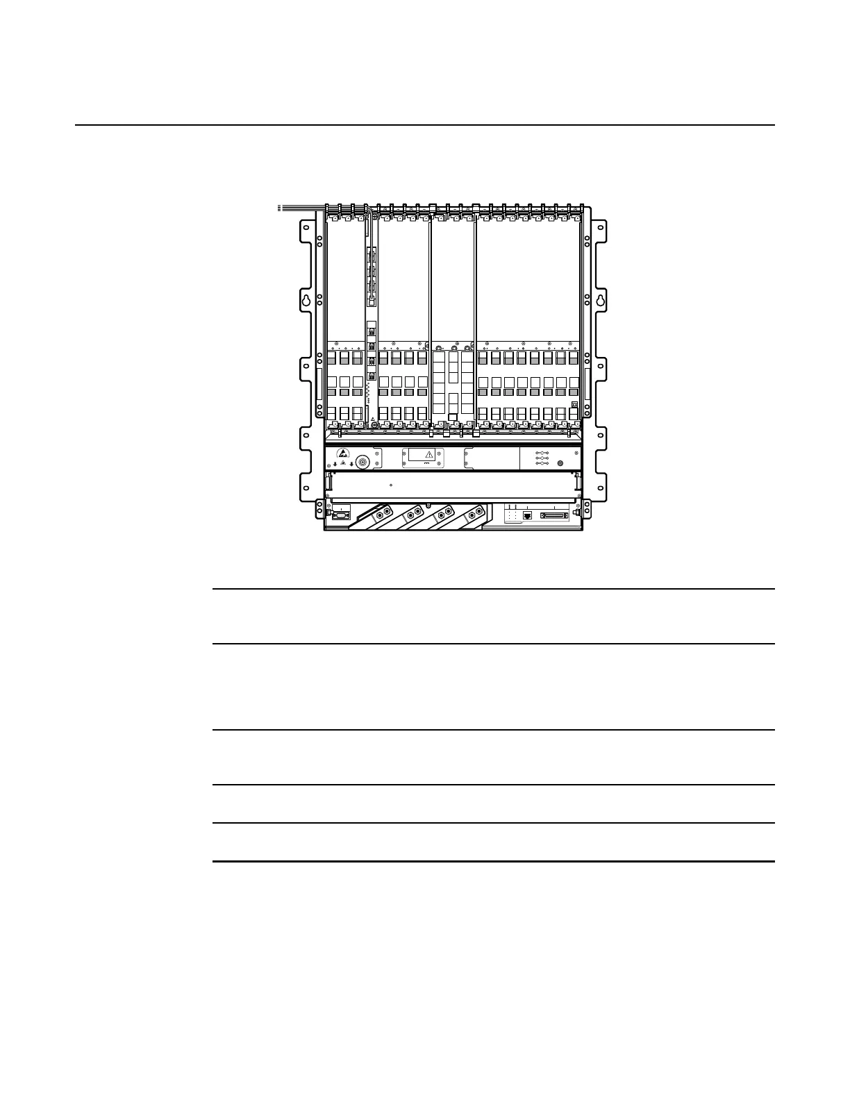
Figure 150 VL cable exit areas
7 Route the other end of the VL cable to an NDLS-E card using the cable management tray
and the cable tie down clips to secure the cable as needed.
8 Connect the VL cable to the VL port on the NDLS-E card by removing the dust cover from
the VL port, removing the cap from the cable connector, and inserting the cable connector
into the VL port. The VL LEDs on the NDLS-E and NDPS-B cards should come on to indicate
that the link is active.
9 Repeat steps 3 to 8 for any additional VL cables that you want to connect between the NDPS-
B card and NDLS-E cards.
10 Re-install the shelf cover or covers removed in step 2.
11 STOP. This procedure is complete.
RING
NT-A
CAUTION: BEFORE REMOVING TERMINAL COVER,
DISCONNECT BOTH “A” AND “B” POWER SOURCES
CAUTION: TORQUE NUTS TO 65 IN-LBS MAX
CRAFT PORT
CO ALARMS
TIME OF DAY
1 Hz-PULSE
BITS INTERFACE
NT-B
TIP
FRAME GND
Energy Hazard
ALM
01 02 03 04 05 06 07 08
NTA
NTIO NTB 09 10 11 12 13 14 15 16
23309
BITS INTERFACE
TIME OF DAY
1 Hz-PULSE
NT-A NT-B
RING
TIP
FRAME GND
CO ALARMS
CRAFT PORT
TB1-2 B
A
T
R
TN A
TB1-
3 B
A
T
RTN B
TB1-1 -4
8V B
AT A
TB1-4 -4
8V B
AT B
CAUTION
ROTATING FAN BLADES
R
T
H
A
E
B
O
N
D
I
N
G
P
O
I
N
T
ESD
CRITICAL
MAJOR
MINOR
BAT A
BAT B
ACO
7360 ISAM FX-16
-48V 70A
Energy Hazard
VL
1
2
3
4
5
6
7
PWR
ACT
ALM
8

 Loading...