7360 ISAM FX-12 shelf cabling
190
ANSI Hardware Installation Manual
3HH-12893-AAAA-TCZZA Issue: 09
DRAFT
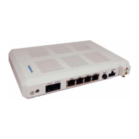
Figure 92 Inserting the cable connector into a VL port on the NDPS-B card
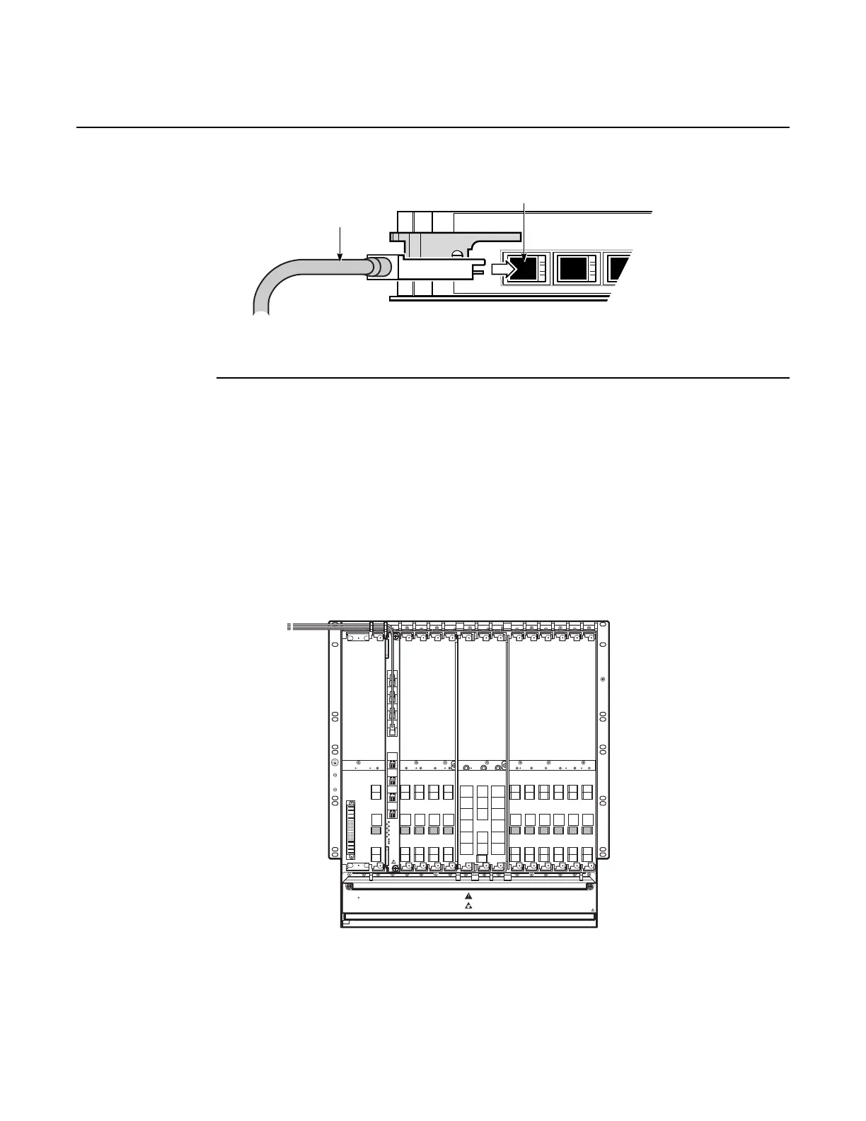
6 Route the VL cable through the appropriate cable exit area of the shelf; see Figure 93 for the
VL cable exit areas:
• for a vertically mounted shelf (cards oriented vertically):
• for a VL cable connected to ports VL1 though VL4 on the NDPS-B card, route the cable
straight up through the cable exit area above the NDPS-B card
• for a VL cable connected to ports VL5 though VL8 on the NDPS-B card, route the cable
up and then towards the PWIO-B card so that the VL cable exists the shelf above PWIO-
B card
Figure 93 VL cable exit areas
23722
VL2VL1
VL cable
VL port
24949
GF C LT1 LT2 LT 3 LT4 LT6
NTA NTB
NTIO
LT5 LT7 LT8 LT9 LT10 LT12LT11
Alarm
ENERGY HAZARD
ROATING FAN BLADES
KEEP FINGERS AWAY FROM
TOP AND BOTTOM OF FAN TRAY
VL
1
2
3
4
5
6
7
PWR
ACT
ALM
8

 Loading...