Connector pinning on NT card
454
ANSI Hardware Installation Manual
3HH-12893-AAAA-TCZZA Issue: 09
DRAFT
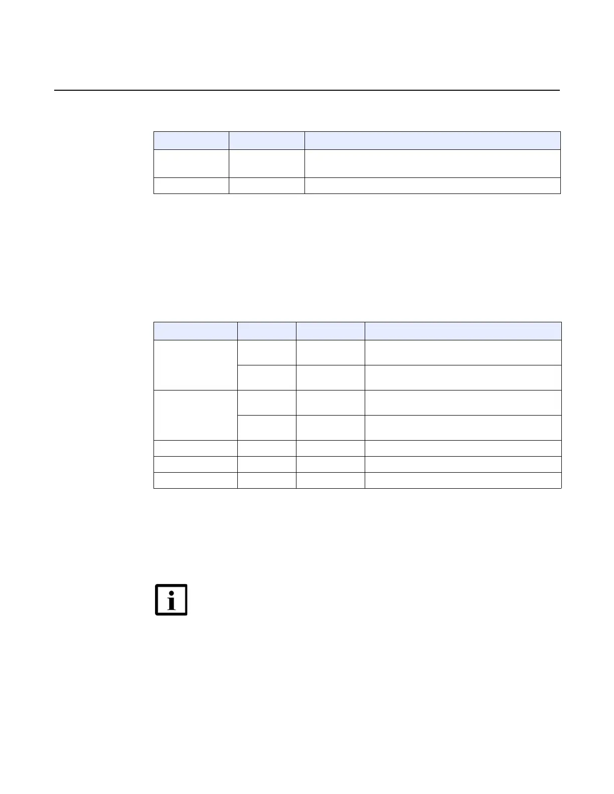
Table 28 10 MHz GPS interface signal list
26.4 ToD/PPS interface signal
Table 29 describes signal and pinning of the ToD/PPS connector on the validation
pulse input interface.
Table 29 ToD/PPS signal list and pinning
26.5 Local craft interface
Table 30 describes the signal and pinning on the local craft interface connector.
Signal name Type Description
10M_GPS-IN Input 10 MHz GPS timing reference
(sine wave, 50Ω, transformer coupled)
Shield Input Frame ground
Signal name Type Pin number Description
ToD_UART_T/F Output 8 ToD UART TX, PTP master mode (differential pair,
100Ω)
Input 7 ToD UART RX, PTP slave mode (differential pair,
100Ω)
ToD_1PPS_T/F Output 6 1 PPS output, PTP master mode (differential pair,
100Ω)
Input 3 1 PPS input, PTP slave mode (differential pair,
100Ω)
EG REF 4,5 Electrical ground
FG REF CASE Frame ground
NC — 1,2 Not connected
Note — Cabling and pinning is dependent on the device
connected to the local craft interface. An example of the DB9
cable pinning is provided in the table, however based on the
specific device used, connections may require alteration.
See your Nokia representative for more information.

 Loading...