Connector pinning of the external interfaces
442
ANSI Hardware Installation Manual
3HH-12893-AAAA-TCZZA Issue: 09
DRAFT
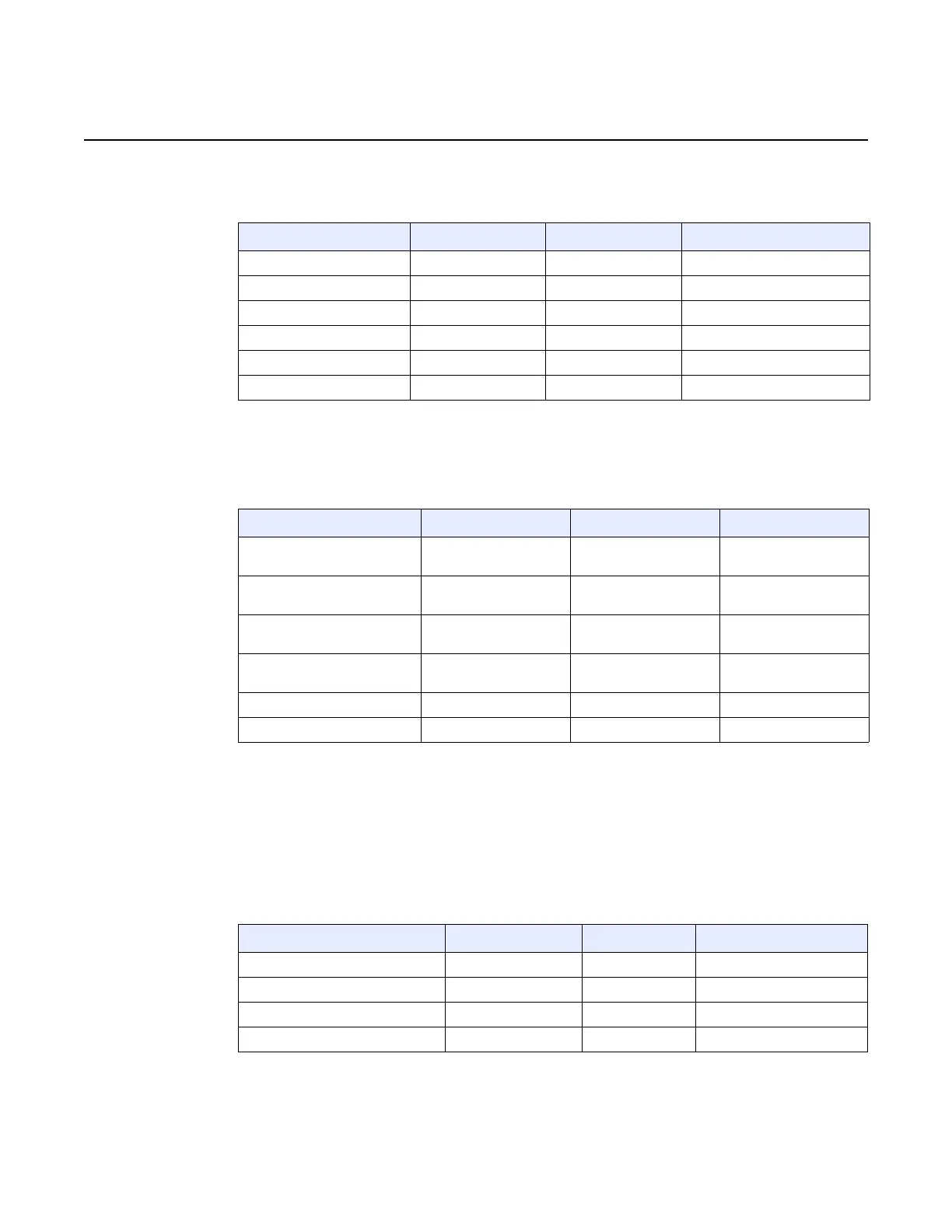
Table 18 BITS interface pinning for 7360 ISAM FX-4, 7360 ISAM FX-8, and
7360 ISAM FX 12
Table 19 describes the BITS interface pinning for the 7360 ISAM FX-16 shelf.
Table 19 BITS interface pinning for 7360 ISAM FX-16
25.3 ToD/1 Hz connector
Table 20 describes the ToD and 1 Hz pinning for the 7360 ISAM FX-16 shelf.
Table 20 ToD/1 Hz pinning for the 7360 ISAM FX-16
Signal name Type Pin number Description
NTB_BITSIN_R Input 1 BITS signal going to NT-B
NTB_BITSIN_T Input 2 BITS signal going to NT-B
FG Input 3 Frame ground ESD
FG Input 4 Frame ground ESD
NTA_BITSIN_R Input 5 BITS signal going to NT-A
NTA_BITSIN_T Input 6 BITS signal going to NT-A
Signal name Type Pin number Description
NTB_BITS_RING Input X225 BITS signal going to
NT-B
NTB_BITS_TIP Input X226 BITS signal going to
NT-B
NTA_BITS_RING Input X227 BITS signal going to
NT-A
NTA_BITS_TIP Input X228 BITS signal going to
NT-A
Frame_GND Input X229 Frame ground
Frame_GND Input X230 Frame ground
Signal name Type Pin number Description
Not connected — 1 No contact
Not connected — 2 No contact
1HZ_RING Input 3 1 Hz signal ring input
SIG_GND Input 4 Electrical ground
(1 of 2)

 Loading...