ANSI Hardware Installation Manual Installing cards in the 7360 ISAM FX-12 shelf
Issue: 09 3HH-12893-AAAA-TCZZA 207
DRAFT
5 Press the insertion/extraction tabs on the front panel to lock the card in place. Attach fixation
screws located at the top and the bottom of the front panel of the card; see Figure 103.
Maximum torque: 2.66 lbf-in. (0.3 N
.
m).
6 The card first displays a heartbeat signal, that is, the green PWR LED is flashing. Then the
card displays an enabling operation signal:
• the green PWR LED is steady on
• the red ALM LED is off
7 In the same way, install all the planned LT cards for the shelf.
8 Install LT card dummy panels in any unused, unpopulated LT card slots to maintain proper
operation.
9 STOP. This procedure is complete.
Procedure 43 To remove cards
Use the following procedure to remove a cards.
1 Put on the antistatic wrist strap and connect it to the earth bonding point at the bottom of the
7360 ISAM FX-12; see Figure 99.
2 Test the ESD wrist strap with the ohmmeter to ensure effectiveness; it must measure 1 MΩ
+/-20% to ground.
3 Loosen the fixation screws located at the top and bottom of the front panel of the card.
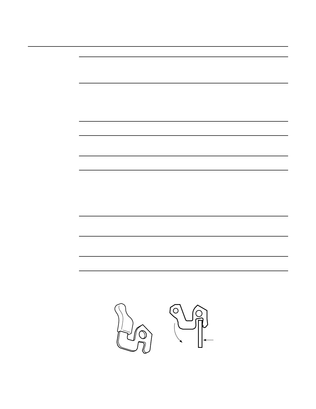
4 Use the ejector handles to disengage the card connectors from the backplane. Figure 104
shows the ejector handles for LT cards. Figure 105 shows the ejector handles for NT cards.
Figure 104 Ejector handles for LT cards
Withdrawl
Guiding plate
22376

 Loading...