ANSI Hardware Installation Manual 7360 ISAM WM shelf cabling
Issue: 09 3HH-12893-AAAA-TCZZA 411
DRAFT
22.5.1.1 Power cable
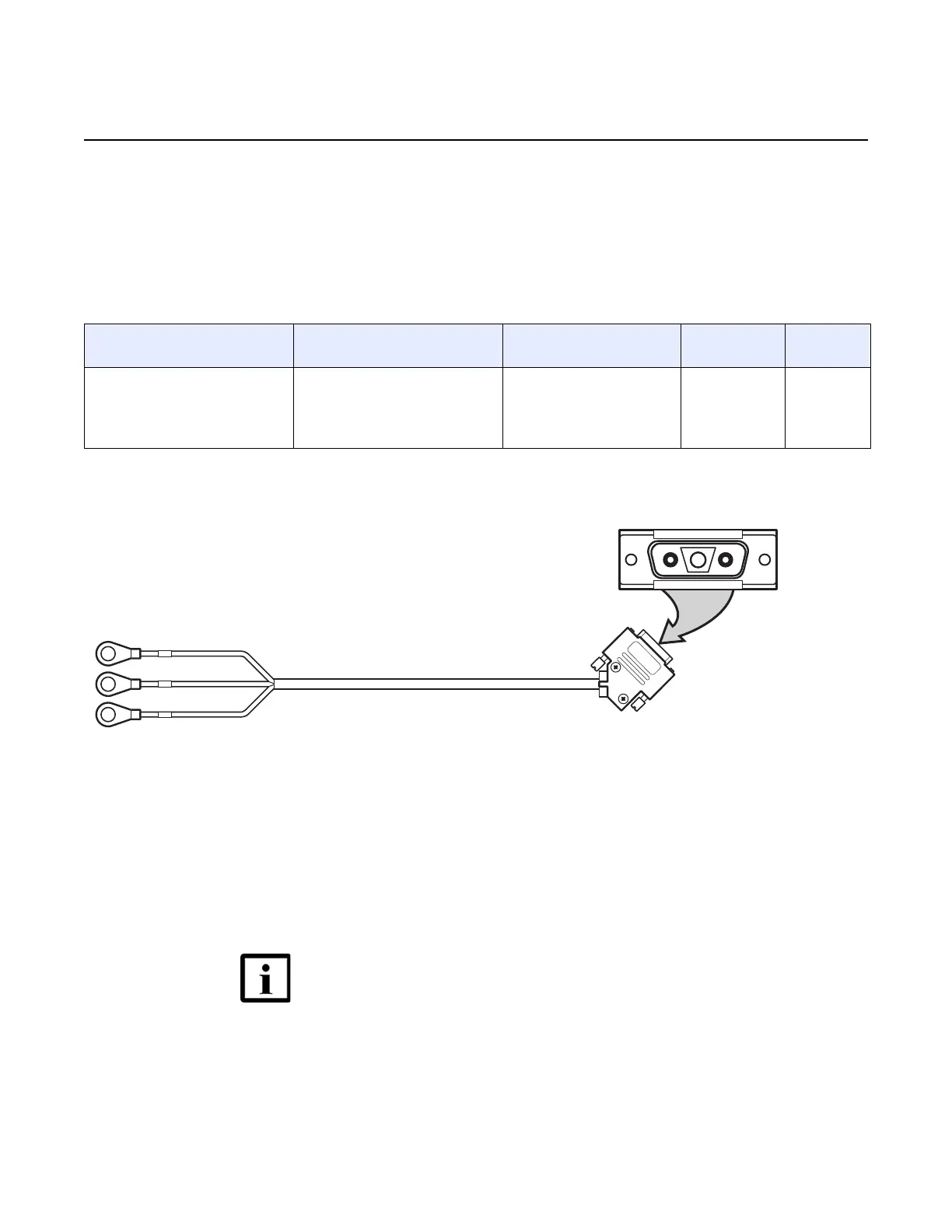
Power cables are routed from the power interface of the 7360 ISAM WM power card
to the power terminals of either the 7360 ISAM FX-16, 7360 ISAM FX-8, or
7360 ISAM FX-4, through the left side of the rack. See Table 17 for the supported
power cable, and see Figure 237 for a view of the supported power cable.
Table 17 Supported 7360 ISAM WM power cable
Figure 237 7360 ISAM WM power cable
22.5.1.2 Power cable routing and connection
The power cable is routed from the FWPC-A at the front of the 7360 ISAM WM,
through the left side of the rack, and connected to the power terminals at the bottom
of the 7360 ISAM FX-16 shelf. See Figure 238 for the location of power terminals on
the 7360 ISAM FX-16, and see Figure 239 for the cabling routing from the
7360 ISAM WM shelf the FX-16 shelf.
Part number Connection point for 3-pin, D-
SUB connector
Connection point for 8 mm
lug
Maximum
current
Maximum
length
3FE 72530 AA FWPC-A power interface PW1.
PW2 is used for power redundancy
(using two 7360 ISAM FX-16
shelves, though this function is not
yet supported).
BAT-A, BAT-B, and
BATRET-A/B on
7360 ISAM FX-16,
7360 ISAM FX-8, or
7360 ISAM FX-4 shelves.
15 A 2 m
Note — The 7360 ISAM WM can also be installed in a rack with
a 7360 ISAM FX-8 or 7360 ISAM FX-4 shelf, with similar
cabling procedures. Contact your Nokia representative for
more information.

 Loading...